Flyback converter utilizing boost inductor between ac source and bridge rectifier
- Summary
- Abstract
- Description
- Claims
- Application Information
AI Technical Summary
Benefits of technology
Problems solved by technology
Method used
Image
Examples
embodiment
Preferred Embodiment
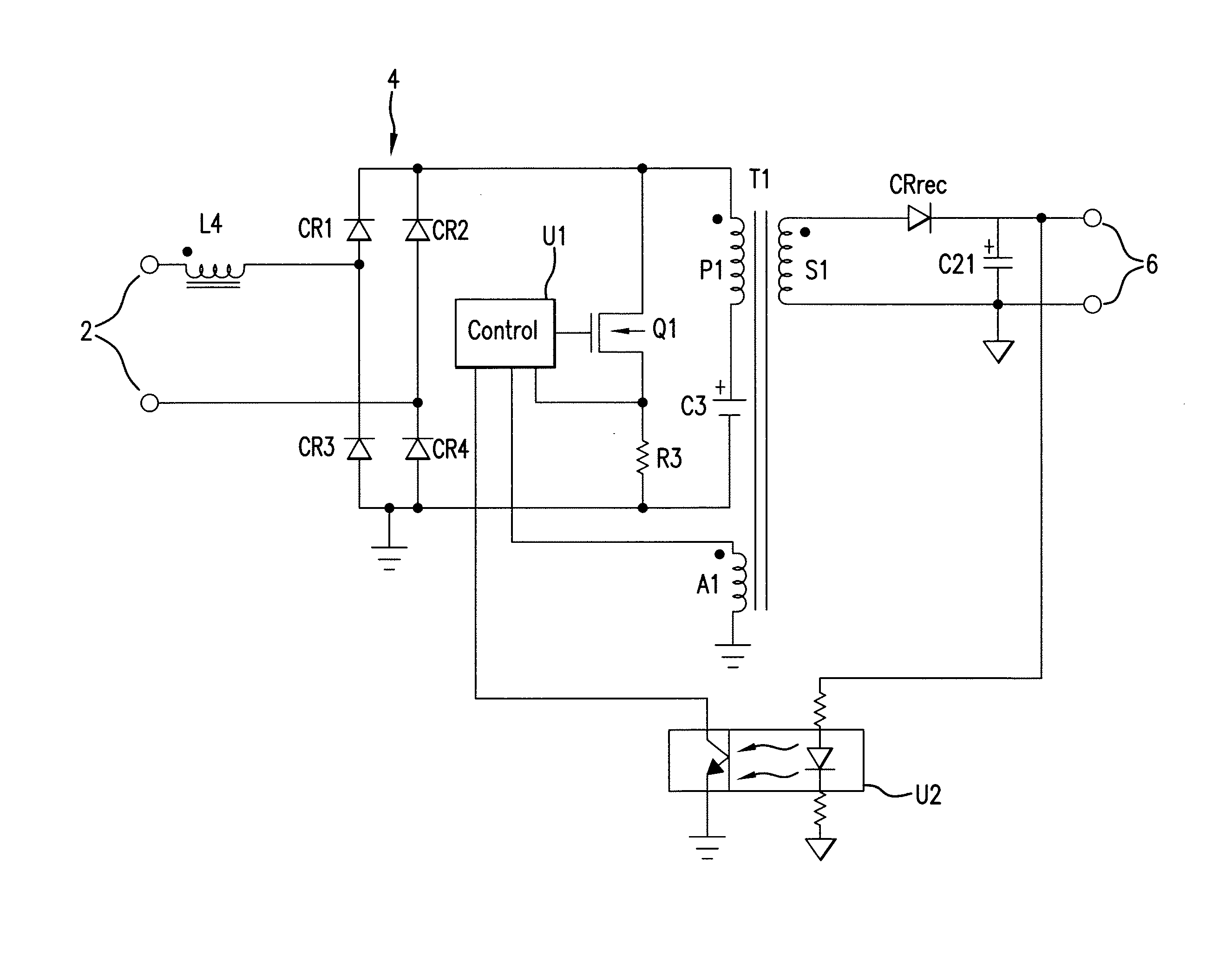
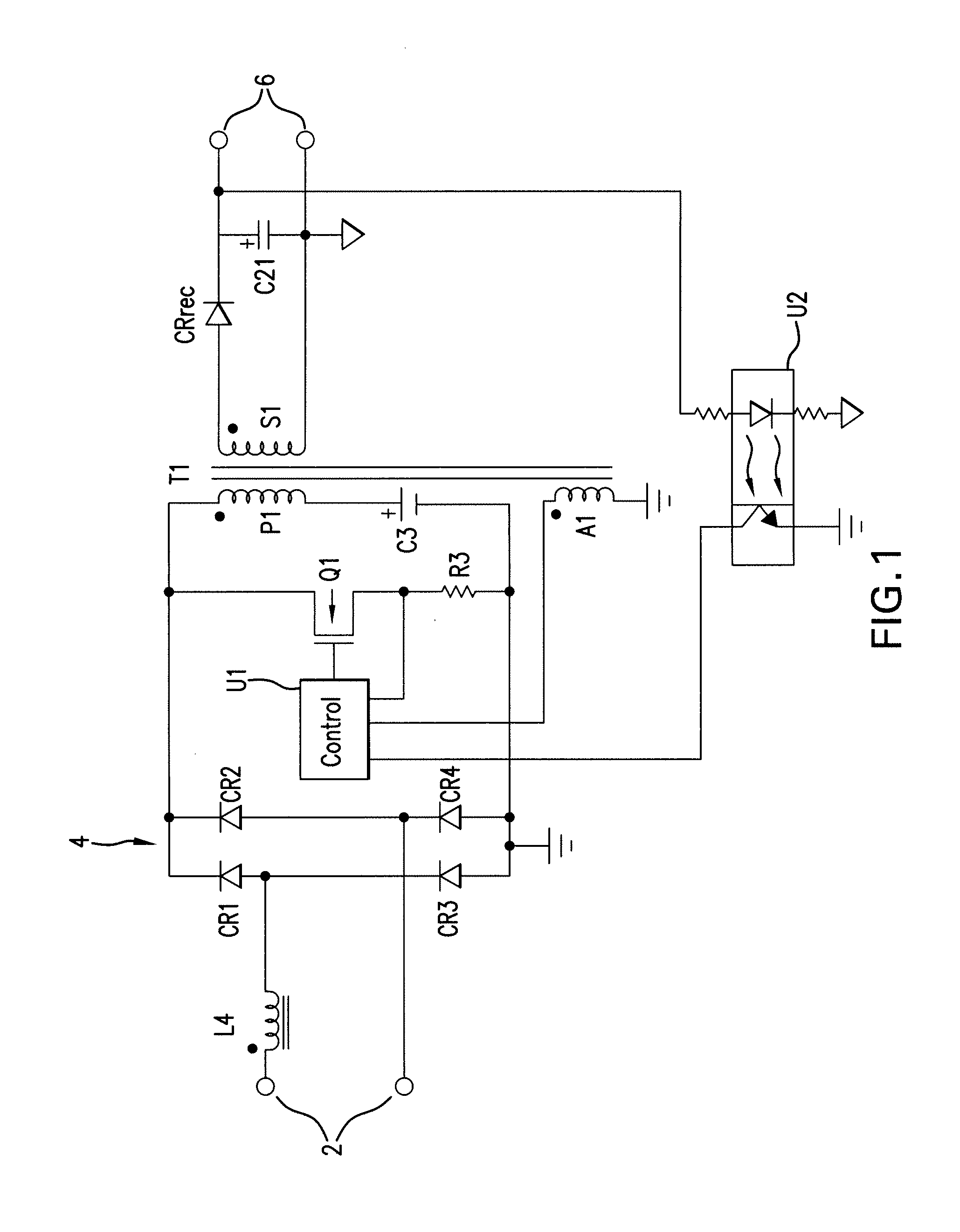
[0019]Referring to FIG. 1, there is shown a combination block diagram / schematic diagram which illustrates a configuration of the invention. A pair of input terminals 2 receives a source of AC power. The applied AC voltage may be 120 VAC at 60 Hz, 240 VAC at 50 Hz or some other values of line voltage and line frequency.
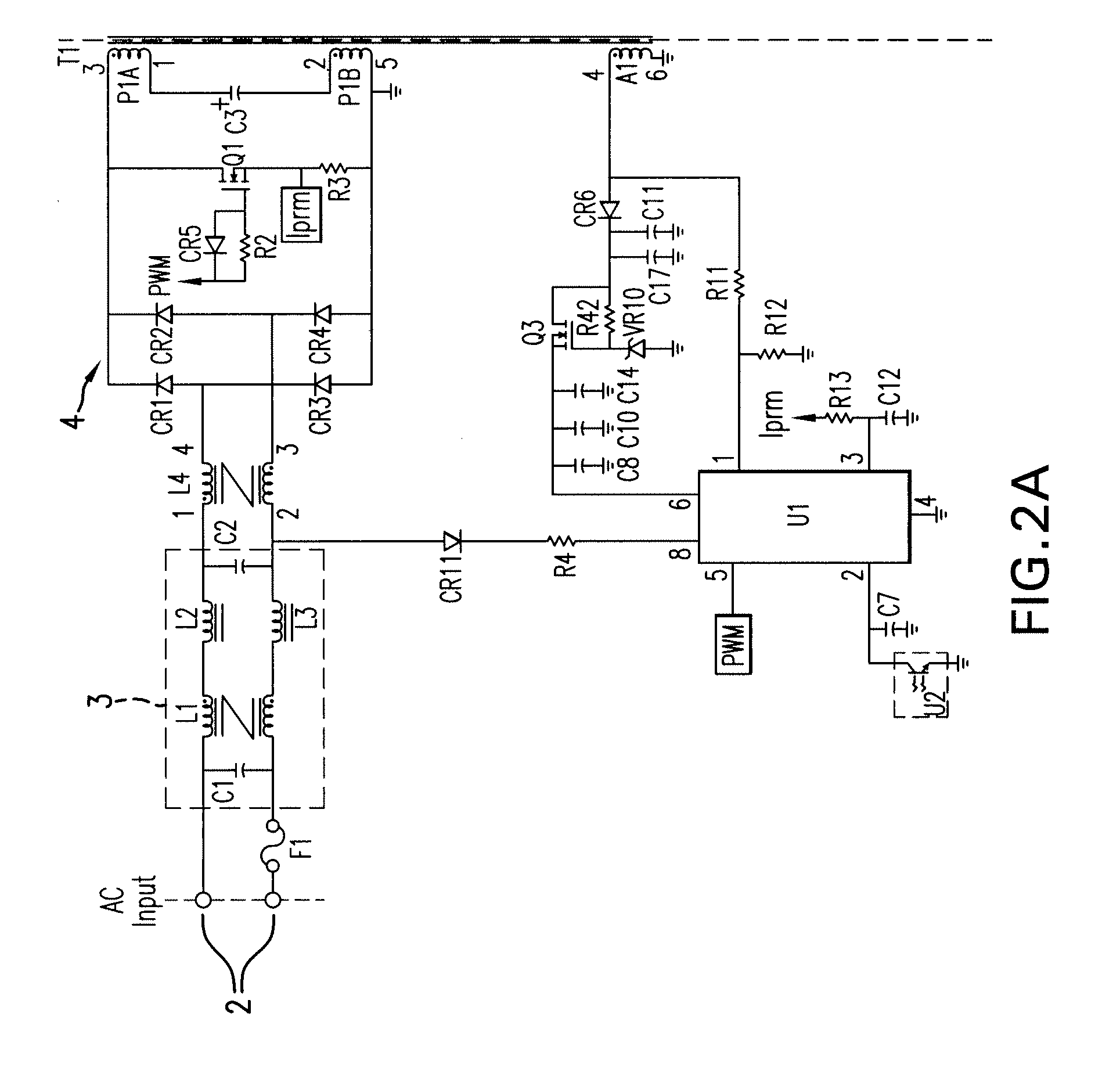
[0020]A boost inductor L4 is coupled at one end of its winding to one of the input terminals 2 and at the other end of its winding to an input of a bridge rectifier 4. The winding is wound around a magnetic core. The bridge rectifier 4 is comprised of diodes CR1-CR4 configured in the usual fashion to provide full wave rectification of the AC input voltage. As explained below, the bridge rectifier also periodically passes current resulting from the release of energy stored in the magnetic core of the boost inductor L4. The second input of the bridge rectifier 4 is coupled to the second of the input terminals 2.
[0021]One of the outputs of the bridge r...
PUM
 Abstract
Description
Claims
Application Information
 - R&D
- Intellectual Property
- Life Sciences
- Materials
- Tech Scout
- Unparalleled Data Quality
- Higher Quality Content
- 60% Fewer Hallucinations
Browse by: Latest US Patents, China's latest patents, Technical Efficacy Thesaurus, Application Domain, Technology Topic, Popular Technical Reports.
© 2025 PatSnap. All rights reserved.Legal|Privacy policy|Modern Slavery Act Transparency Statement|Sitemap|About US| Contact US: help@patsnap.com


