
MIMO channel loopback

a loopback and channel technology, applied in multi-frequency code systems, transmission path sub-channel allocation, duplex signal operation, etc., can solve the problems of large volume of channel feedback, large amount of processing, and inability to provide channel state information. to be of any use, so as to achieve efficient channel feedback large volume

Inactive Publication Date: 2011-06-23
TELEFON AB LM ERICSSON (PUBL)
View PDF3 Cites 23 Cited by
  • Summary
  • Abstract
  • Description
  • Claims
  • Application Information

AI Technical Summary

Benefits of technology

The present invention provides a method for efficiently providing a large volume of channel feedback to a remote transmitter in OFDM MISO and MIMO systems. The method maps channel feedback values to individual transmission subchannels in a one-to-one correspondence, which reduces the amount of feedback required and improves the overall efficiency of the communication. The feedback values can include reference signal values or channel estimates derived from received reference values. The invention can be used in both uplink and downlink channels, and can be used with both fixed and mobile stations. The feedback values can also include data signal values received on a reception subchannel and mapped to a transmission subchannel.

Problems solved by technology

The problem with digitally coded feedback is that in situations where the channel changes rapidly, the channel state information arrives too late to be of any use.
However, the compression algorithms may quantize the channel data too coarsely, or, at the current state of the art, may require an excessive amount of processing.
Thus, OFDM requires a large volume of channel feedback, particularly when used in MISO and MIMO systems.
When this requirement is coupled with rapidly changing channels, e.g., when the receiver or transmitter is moving at a high rate of speed, OFDM faces some unique channel feedback challenges.

Method used


Image

  • MIMO channel loopback
  • MIMO channel loopback
  • MIMO channel loopback

Examples


Embodiment Construction

l OFDM transmitter.

[0015]FIG. 3 shows a general OFDM receiver.

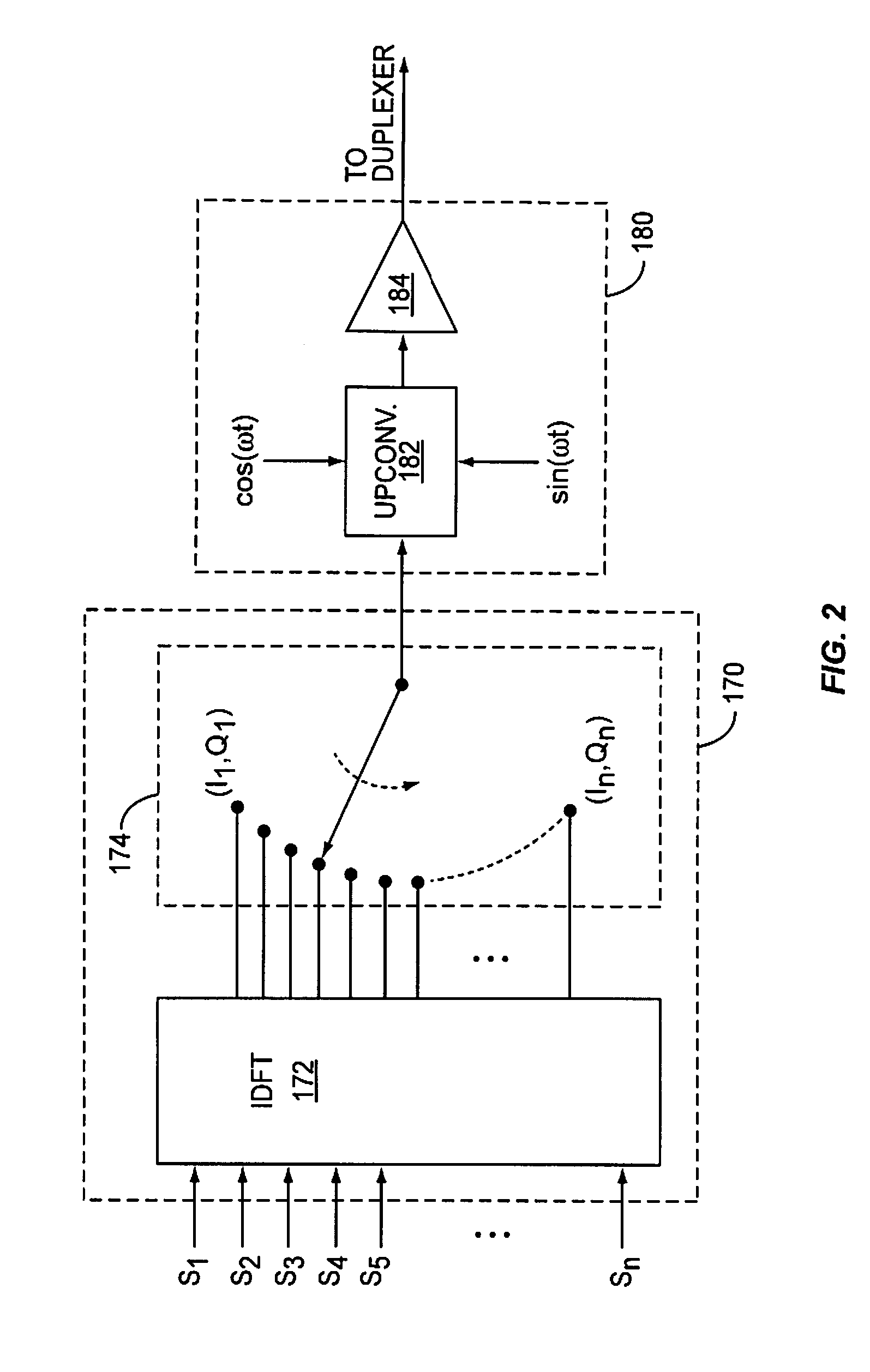
[0016]FIG. 4 shows another general OFDM transmitter.

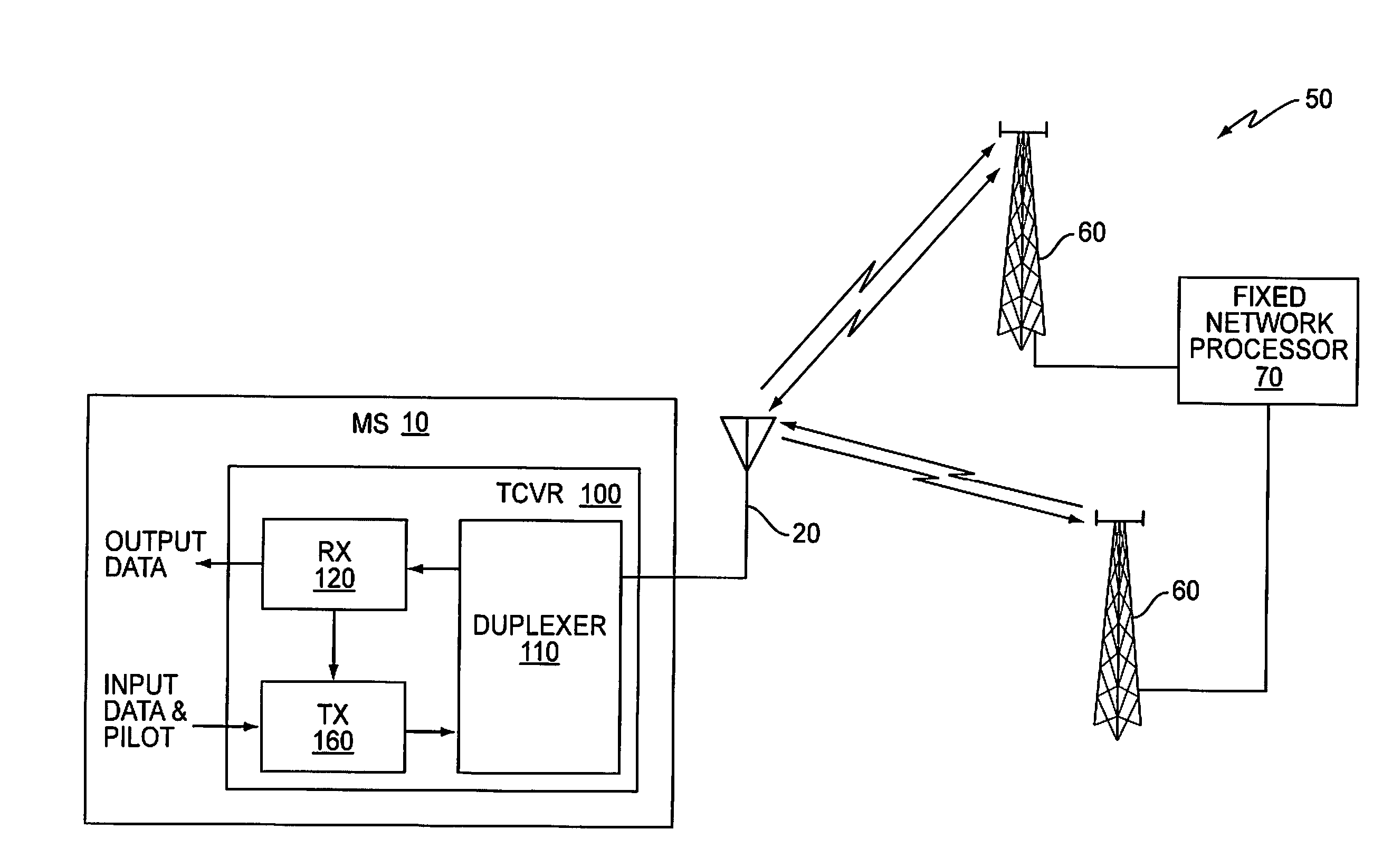
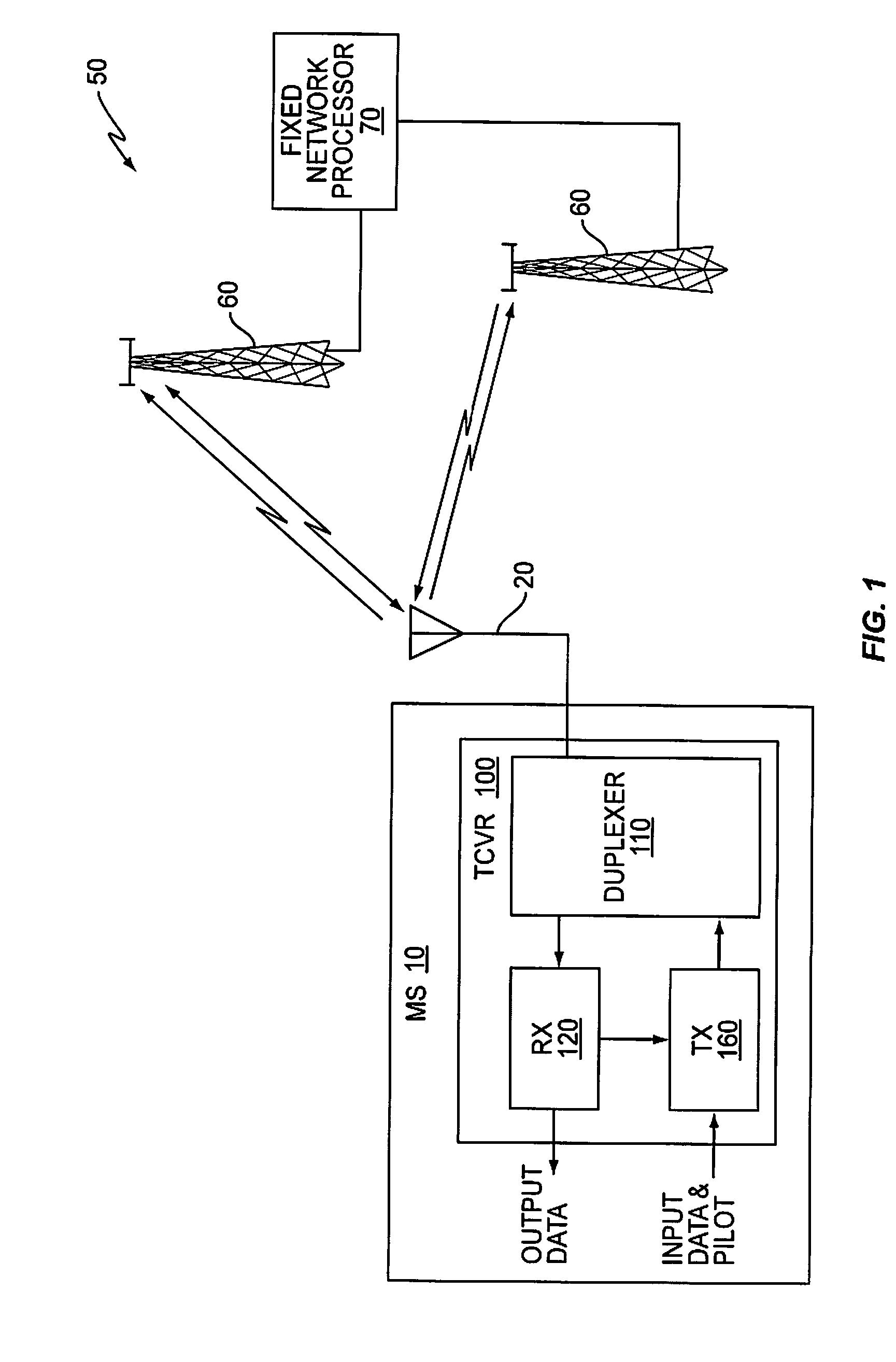
[0017]FIG. 5 shows a diagram of a transceiver according to one exemplary embodiment of the present invention.

[0018]FIG. 6 shows an exemplary time multiplexing scheme for sharing OFDM subcarriers between data values and feedback values.

DETAILED DESCRIPTION

[0019]The invention described herein provides timely channel feedback for multi-carrier systems, e.g., OFDM-MISO and OFDM-MIMO systems. To that end, the present invention provides an OFDM transceiver that receives a downlink reference value, e.g., a pilot signal, on a corresponding reception subcarrier of an OFDM signal received from a remote transceiver. The receiving transceiver maps a feedback value to a single transmission subcarrier of an outgoing OFDM signal, where the feedback value comprises a downlink reference value, e.g., pilot signal, or a channel estimate derived therefrom. The OFDM transceiver subsequently ...


PUM


Abstract

A method and apparatus for efficiently providing a large volume of channel feedback, e.g., for OFDM MISO and MIMO systems, is described herein. To that end, a mapping unit in an OFDM transceiver maps channel feedback values, e.g., received reference signal values or channel estimates derived therefrom, on a one-to-one basis to individual transmission subchannels. More particularly, the mapping unit maps a feedback value, e.g., the received reference value or a channel estimate derived therefrom, to a single transmission subchannel of an outgoing OFDM signal. For example, the mapping unit may map the feedback value to an input of a frequency transform unit, such as an inverse discrete Fourier transform unit, to map the feedback value to a single transmission subchannel comprising an OFDM transmission subcarrier. The OFDM transceiver transmits the outgoing OFDM signal to the remote transceiver to provide the feedback value to the remote transceiver.

Description

BACKGROUND[0001]The present invention is generally directed to providing channel feedback in a wireless system, and more particularly directed to providing channel feedback in orthogonal frequency division multiplex (OFDM) multiple-input, multiple-output (MIMO) wireless systems.[0002]Wireless communications systems increasingly seek ways to improve signal quality and / or increase the data rate. One solution uses multiple antennas at the transmitter to implement multiple-input, single-output (MISO) operations. Multiple transmitting antennas may be used in different ways, depending on the relative location of the transmitting antennas. If the transmitting antennas are closely spaced, e.g., on the order of a wavelength or less, they can be used in an array for forming a directional beam. If, on the other hand, the transmitting antennas are more widely spaced, e.g., on different sites, they can be used to provide non-coherent or coherent macrodiversity. In non-coherent macrodiversity, th...

Claims


Application Information

Patent Timeline
Patent Type & Authority Applications(United States)
IPC IPC(8): H04L27/28H04B1/38
CPCH04L5/0048H04L5/0057H04L5/0053
Inventor DENT, PAUL W.
Owner TELEFON AB LM ERICSSON (PUBL)
Learn More