Residential integrated ventilation energy controller

a technology of integrated ventilation and energy controller, which is applied in the direction of ventilation systems, lighting and heating apparatus, heating types, etc., can solve the problems of contaminant build-up within the house that can quickly become unacceptable, the integrated approach to looking at residential indoor air quality is usually lacking, and the indoor air quality is complex, so as to reduce energy and peak power, and effectively maintain the home air quality

Inactive Publication Date: 2011-06-23
RGT UNIV OF CALIFORNIA
View PDF33 Cites 37 Cited by
  • Summary
  • Abstract
  • Description
  • Claims
  • Application Information

AI Technical Summary

Benefits of technology

[0012]By way of this invention, a smart fan controller is provided that can substantially reduce the energy and peak power required to provide mechanical ventilation to a home in a way that effectively maintains home air quality. The smart fan controller achieves this by communicating with other exhaust or supply air systems in the home, such as those commonly found in bathrooms, kitchens, dryers, and the like, and controlling the operation of the whole-house ventilation fan which comprises a vital component of the mechanical ventilation system, turning it off (or down in the case where the fan can operate at variable speeds) in response to the status of other exhaust and supply fans in the home. In one embodiment, the smart fan control

Problems solved by technology

Indoor air quality is a complex result of occupant activities, human responses, source emission, and contaminant removal.
Virtually every building code contains requirements related to ventilation and indoor air quality, but an integrated approach to looking at residential indoor air quality is usually lacking.
However, as a consequence of air tightness requirements needed to meet such mandated energy efficiencies, without provision for ventilation, contaminant build up within the house can quickly become unacceptable.
However, these simple solutions cannot be relied upon for adequate ventilat

Method used


Image

  • Residential integrated ventilation energy controller
  • Residential integrated ventilation energy controller
  • Residential integrated ventilation energy controller

Examples


Embodiment Construction

[0021]New homes in some jurisdictions are required to meet the ASHRAE Standard on residential ventilation (62.2-2007). This standard specifies minimum continuous mechanical ventilation rates. While it does not specifically address the issues of source control or ventilation load shifting, it does allow alternative approaches to be used if they can be shown to provide equivalent performance.

[0022]Existing building stock is substantially leakier than typical new construction. Despite the natural and increasingly legal incentives to control energy costs, a key barrier to improved envelope air tightness is the real concern that indoor air quality will be compromised. Unlike new construction, existing homes have no mandate to meet any ventilation or indoor air quality standard. Thus, if air tightness is to be improved, provision at the same time needs to be made for maintenance of indoor air quality.

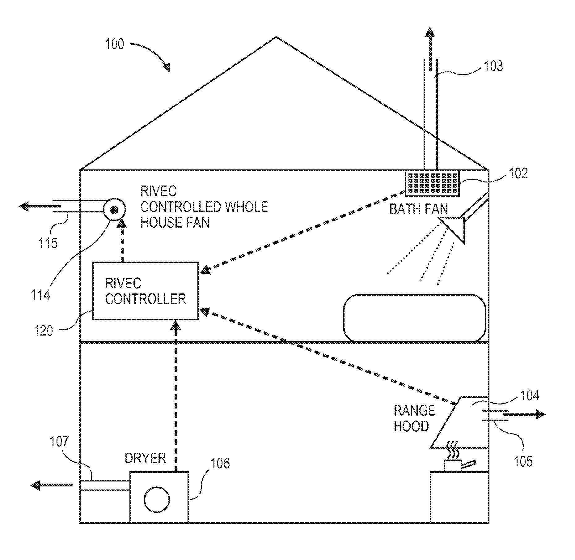
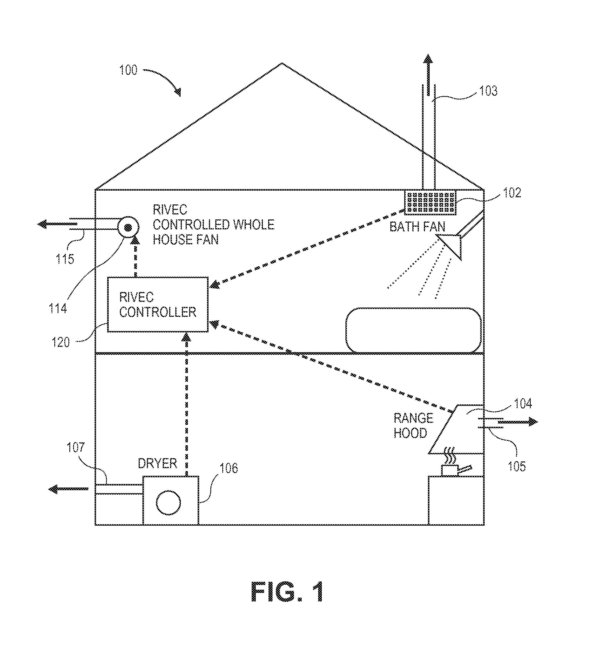
[0023]To address this indoor air quality issue, a low cost, energy efficient home ventila...


PUM


Abstract

A residential controller is described which is used to manage the mechanical ventilation systems of a home, installed to meet whole-house ventilation requirements, at the same time reducing energy costs. This is achieved in part by shifting the ventilation load of the whole-house system to off peak hours and by taking into account exogenous mechanical ventilation induced by other systems. The controller is linked by wire or wirelessly to other house ventilation systems using any one of a number of communication protocols, sensing the on-off status of such exogenous systems. An operational algorithm preloaded and/or modified at the point of use is used to control the on-off status or fan speed of a whole-house ventilation fan which forms a part of the home ventilation system, the operating status of the whole-house fan in part responsive to the status of other home ventilation systems, and in part based on time of day.

Description

CROSS REFERENCE TO RELATED APPLICATIONS[0001]This Non Provisional US patent application claims priority to U.S. Provisional Patent Application No. 61 / 287,356, filed Dec. 17, 2009, entitled Residential Integrated Ventilation Energy Controller, the contents of said application incorporated in its entirety, as if fully set forth herein.STATEMENT OF GOVERNMENTAL SUPPORT[0002]The invention described and claimed herein was made in part utilizing funds supplied by the U.S. Department of Energy under Contract No. DE-AC02-05CH11231 between the U.S. Department of Energy and the Regents of the University of California for the management and operation of the Lawrence Berkeley National Laboratory. The government has certain rights in this invention.BACKGROUND OF THE INVENTION[0003]1. Field of the Invention[0004]This invention relates generally to ventilation systems for residential homes, designed to meet new and emerging air quality standards, and more specifically to a programmed / programmable ...

Claims


Application Information

Patent Timeline
IPC IPC(8): F24F11/00
CPCF24F7/007F24F11/0001Y02B30/767F24F2011/0075F24F2011/0091F24F2011/0068F24F11/56F24F11/46F24F11/52
Inventor SHERMAN, MAXWALKER, IAINDICKERHOFF, DARRYL
Owner RGT UNIV OF CALIFORNIA
Why Eureka
Try Eureka