
Production method of rotating device having thrust dynamic pressure generating site on which a thrust pressure pattern is formed and rotating device produced by said production method

a technology of rotating device and thrust dynamic pressure, which is applied in the direction of metal-working feeding device, manufacturing tools, instruments, etc., can solve the problems of reducing the rotational accuracy of foreign particles, affecting the efficiency of lubricant raking, and bearing malfunction, so as to improve the efficiency of raking up lubricant, improve the efficiency of lubricant raking, and narrow down the bearing gap

Inactive Publication Date: 2011-06-30
SAMSUNG ELECTRO MECHANICS JAPAN ADVANCED TECHNOLOGY CO LTD
View PDF8 Cites 5 Cited by
  • Summary
  • Abstract
  • Description
  • Claims
  • Application Information

AI Technical Summary

Benefits of technology

The present invention provides a method for producing a rotating device with improved efficiency and reduced deformation of the thrust dynamic pressure pattern. This is achieved by narrowing down the bearing gap and raking up the lubricant effectively. The method includes steps of setting the rotating member or fixed member in a manufacturing apparatus, marking a step portion on the member, applying a pressing force to the member, and incorporating the member into the rotating device. The thrust dynamic pressure pattern is formed while applying a small supplemental force to maintain the state of contact with the member. The rotating device can be used for driving a recording disk or for mounting and rotationally driving a recording disk.

Problems solved by technology

When the height variation of the protrusions of the thrust dynamic pressure pattern is large, the area with the most height comes into contact with the opposite surface that the thrust dynamic pressure pattern faces when the gap between the opposite surface and the thrust dynamic pressure pattern is narrowed down, and the area with the most height is scraped due to contact with the opposite surface, which results in foreign particles.
The existence of foreign particles in a bearing reduces the rotational accuracy.
In the worst case scenario, a bearing malfunction, such as a burn-in, may be caused.
Therefore, the gap between the thrust dynamic pressure pattern and the opposite surface cannot be greatly narrowed down.
When the shape of the protrusion of the thrust dynamic pressure pattern is greatly deformed, a steep edge cannot be obtained, and the lubricant cannot be efficiently raked up.
Therefore, the efficiency of dynamic pressure generation is low, and the stiffness of the bearing cannot be improved.
In other words, a large deformation of the shape of the protrusion of the thrust dynamic pressure pattern and a large variation in the height of the protrusion prevents the stiffness of the bearing from being improved.

Method used


Image

  • Production method of rotating device having thrust dynamic pressure generating site on which a thrust pressure pattern is formed and rotating device produced by said production method
  • Production method of rotating device having thrust dynamic pressure generating site on which a thrust pressure pattern is formed and rotating device produced by said production method
  • Production method of rotating device having thrust dynamic pressure generating site on which a thrust pressure pattern is formed and rotating device produced by said production method

Examples


Embodiment Construction

[0025]The invention will now be described by reference to the preferred embodiments. This does not intend to limit the scope of the present invention, but to exemplify the invention.

[0026]The invention will now be described in reference to the preferred embodiments (hereinafter, referred to as embodiments). The same or equivalent constituting elements and members illustrated in each drawing shall be denoted by the same reference numerals, and duplicative explanations will be omitted appropriately. The dimensions of members illustrated in each drawing are appropriately enlarged or reduced for easier understanding. Some of members not important for describing the embodiments are omitted from each drawing.

[0027]Preferably, a rotating device produced by the production method of the embodiment is used as a Hard Disk Drive (often simply referred to as an HDD or a rotating device) on which a recording disk is mounted.

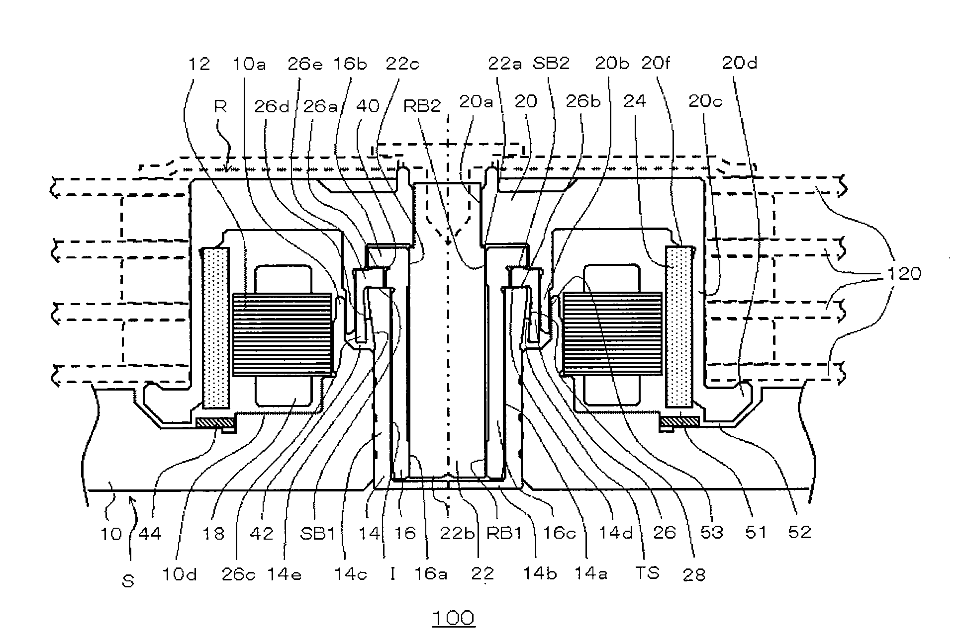
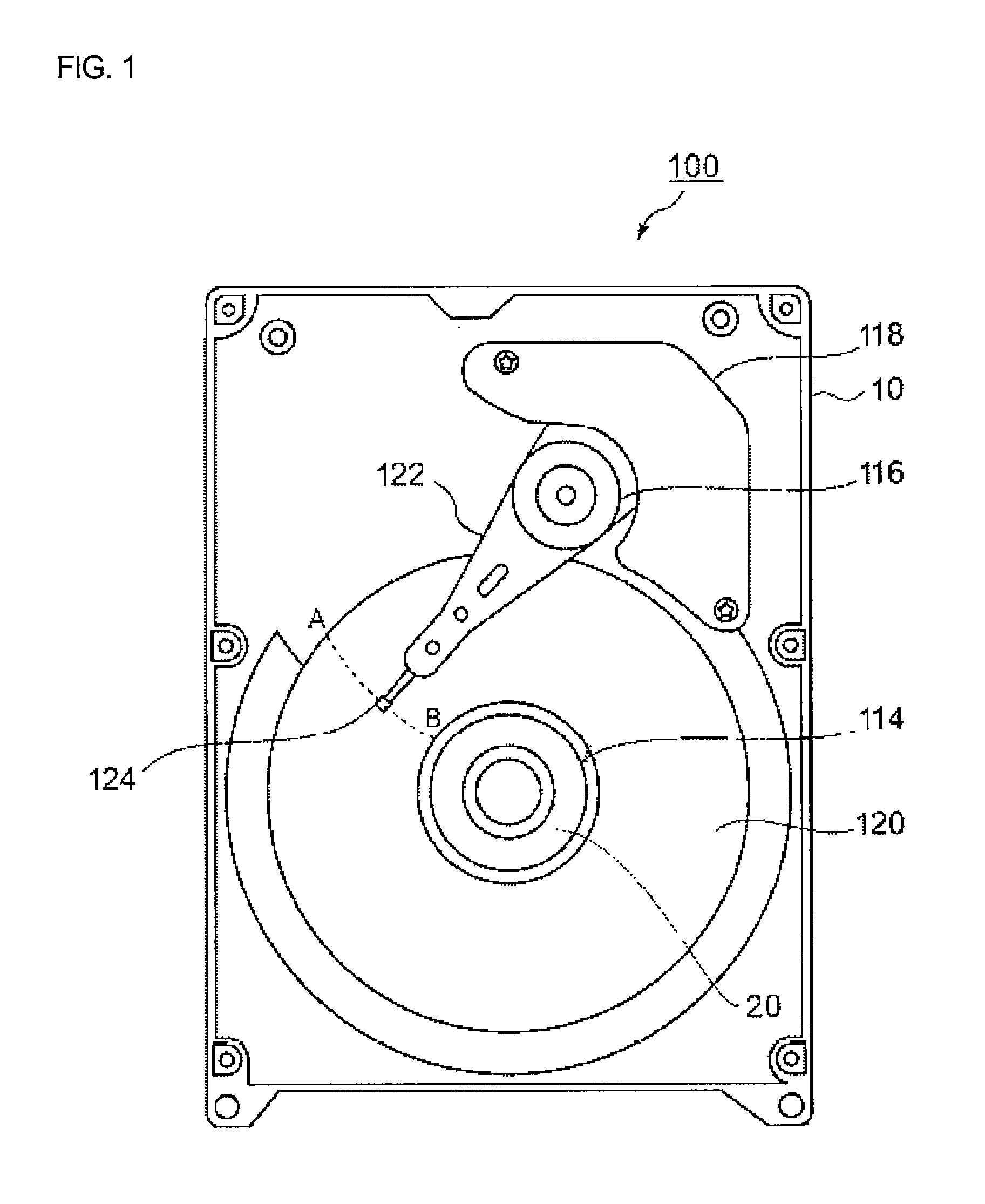
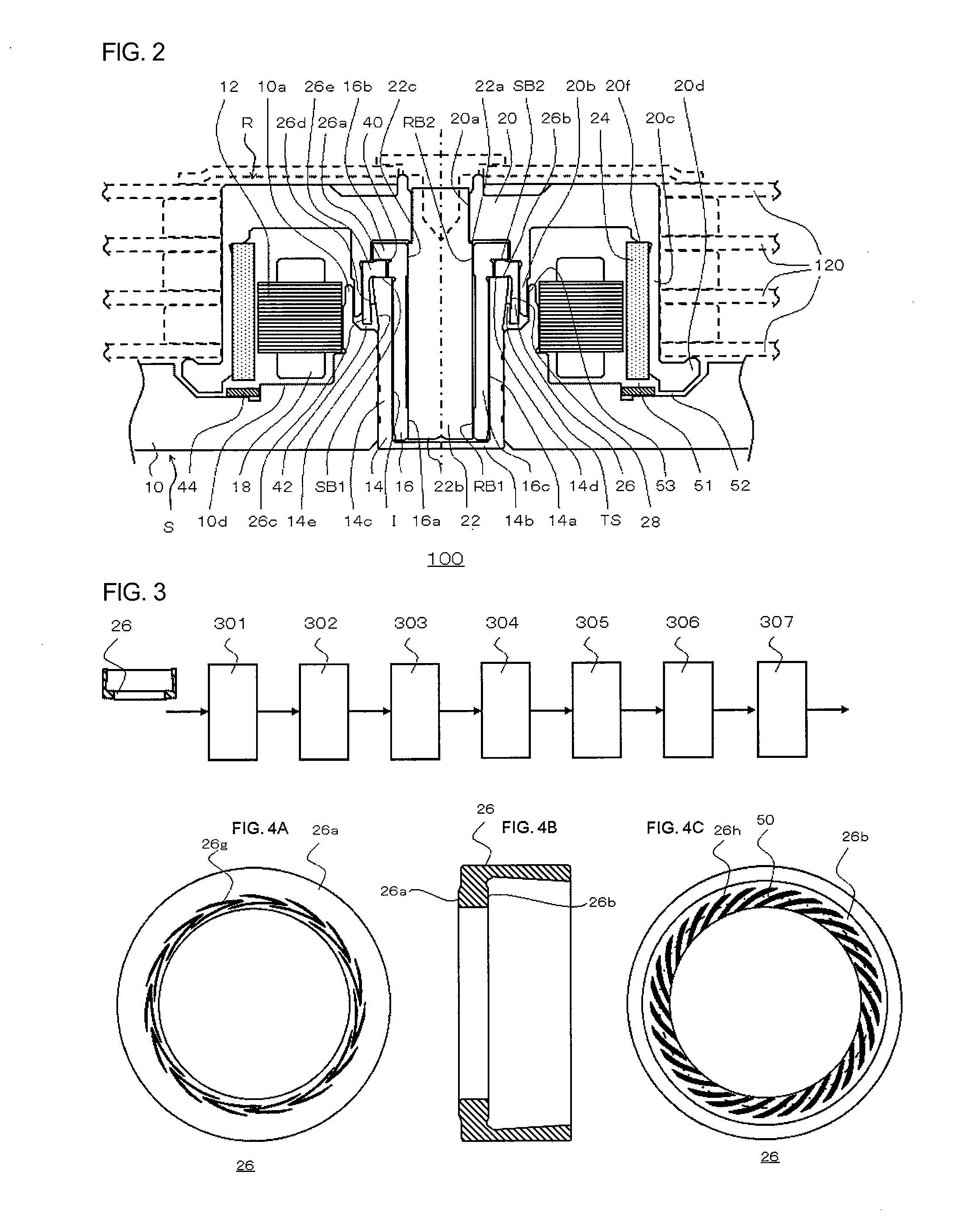
[0028]FIG. 1 is an illustrative view illustrating the internal structure ...


PUM

PropertyMeasurementUnit
supplemental forceaaaaaaaaaa
pressing forceaaaaaaaaaa

Abstract

A thrust dynamic pressure pattern is marked on a rotating member or fixed member set on a rest table. A pressure for marking is applied to a member to be marked in a cycle of applying and releasing the pressure, and a supplemental force for keeping the member to be marked, still is separately applied. According to the present embodiment, a rotating device can be provided that narrows down a bearing gap and improves the efficiency of raking up a lubricant so as to increase the dynamic pressure by reducing the deformation of the shape of the protrusions of a thrust dynamic pressure pattern and the variation in the height of the protrusions when forming the thrust dynamic pressure pattern in a method of producing a rotating device.

Description

CROSS-REFERENCE TO RELATED APPLICATION[0001]This application is based upon and claims the benefit of priority from International application PCT / JP2009 / 007325, filed on Dec. 28, 2009 and Japanese Patent Application No. JP 2010-121575, filed on May 27, 2010, the entire content of which is incorporated herein by reference.BACKGROUND OF THE INVENTION[0002]1. Field of the Invention[0003]The present invention relates to a production method of a rotating device and particularly to a production method of a rotating device, which improves the processing accuracy of a thrust dynamic pressure pattern and provides a rotating device with enhanced bearing stiffness, and to a rotating device produced by the method.[0004]2. Description of the Related Art[0005]There exists a rotating device such as a Hard Disk Drive (HDD) in which a fluid dynamic bearing unit, which allows for stable high-speed rotation, is mounted. An example of the structure of the fluid dynamic bearing unit is a fluid dynamic be...

Claims


Application Information

Patent Timeline
Patent Type & Authority Applications(United States)
IPC IPC(8): B21D43/02
CPCB21K1/04B21K23/00F16C17/045G11B19/2036Y10T29/49673F16C33/14F16C2220/40Y10T29/49639F16C2370/12F16C2220/70F16C2223/42F16C2223/70F16C2223/80F16C2226/12F16C2226/40
Inventor FUKUZAKO, YASUOIWAI, HIROSHI
Owner SAMSUNG ELECTRO MECHANICS JAPAN ADVANCED TECHNOLOGY CO LTD
Learn More