
Apparatus for determining an abnormality of a control valve of an internal combustion engine

a control valve and abnormality technology, applied in the direction of electrical control, machines/engines, instruments, etc., can solve the problems of not being able to determine whether or not the intake air changeover valve operates normally, and not being able to find abnormalities of exhaust gas changeover valves

Inactive Publication Date: 2011-06-30
TOYOTA JIDOSHA KK
View PDF9 Cites 31 Cited by
  • Summary
  • Abstract
  • Description
  • Claims
  • Application Information

AI Technical Summary

Benefits of technology

[0093]In the second control valve which is configured as above, the first pressure can be changed by changing a magnitude of the biasing force of the biasing means. Hereinafter, control valve which has the configuration as described above will be referred to as “an automatically-open-and-close-valve” for convenience.

Problems solved by technology

However, the utility model does not disclose how to determine whether or not the intake air changeover valve operates normally at all.
Further, in the conventional apparatus, the abnormality of the exhaust gas changeover valve can not be found until when an actual supercharging pressure becomes larger than the predetermined maximum value of the supercharging pressure, even if the exhaust gas changeover valve is abnormal.
Therefore, in the conventional apparatus, the abnormality of the exhaust gas changeover valve can not be found when the engine is operated in an area other than the high load operating area.

Method used


Image

  • Apparatus for determining an abnormality of a control valve of an internal combustion engine
  • Apparatus for determining an abnormality of a control valve of an internal combustion engine
  • Apparatus for determining an abnormality of a control valve of an internal combustion engine

Examples


first embodiment

A First Embodiment

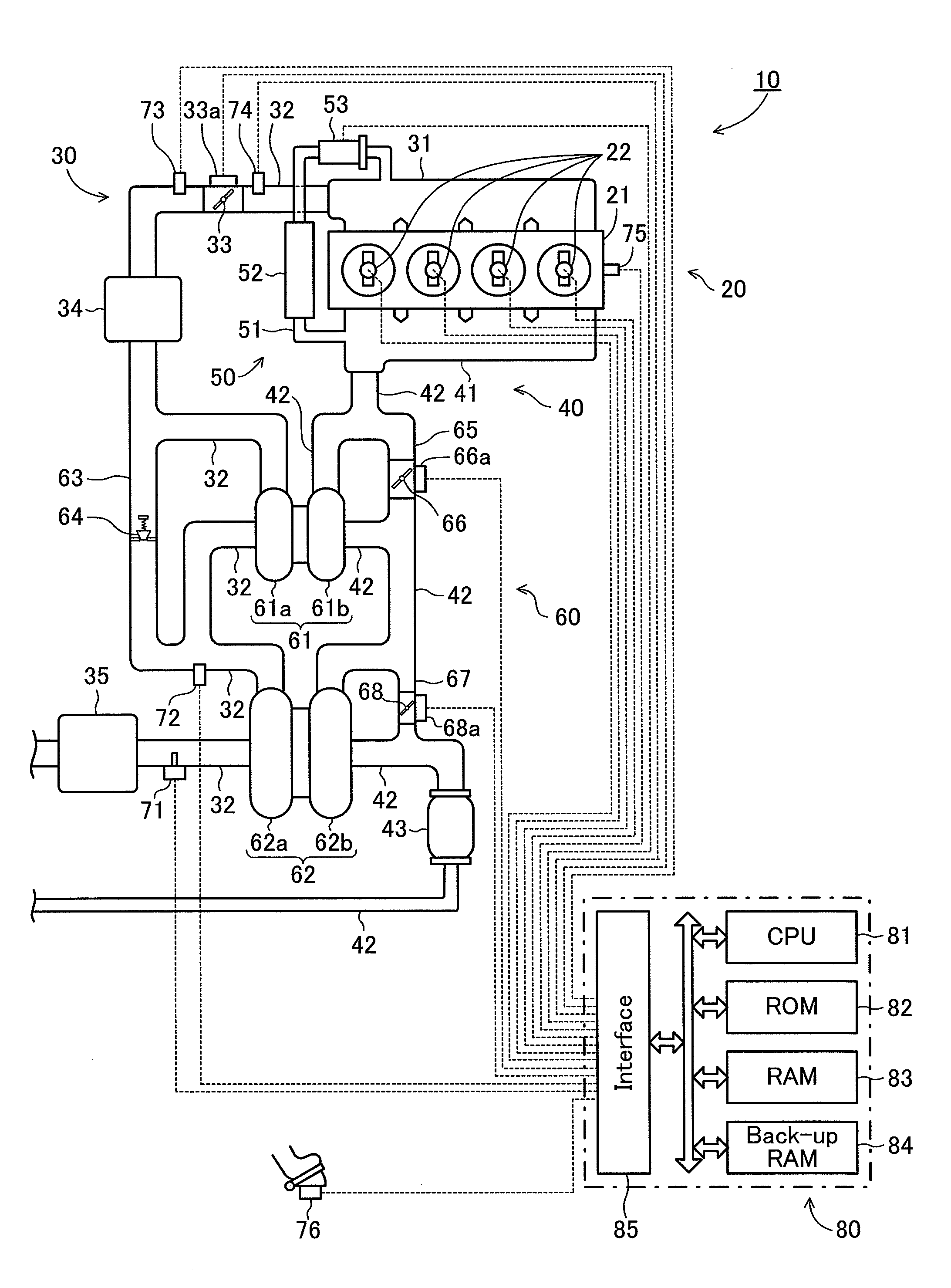
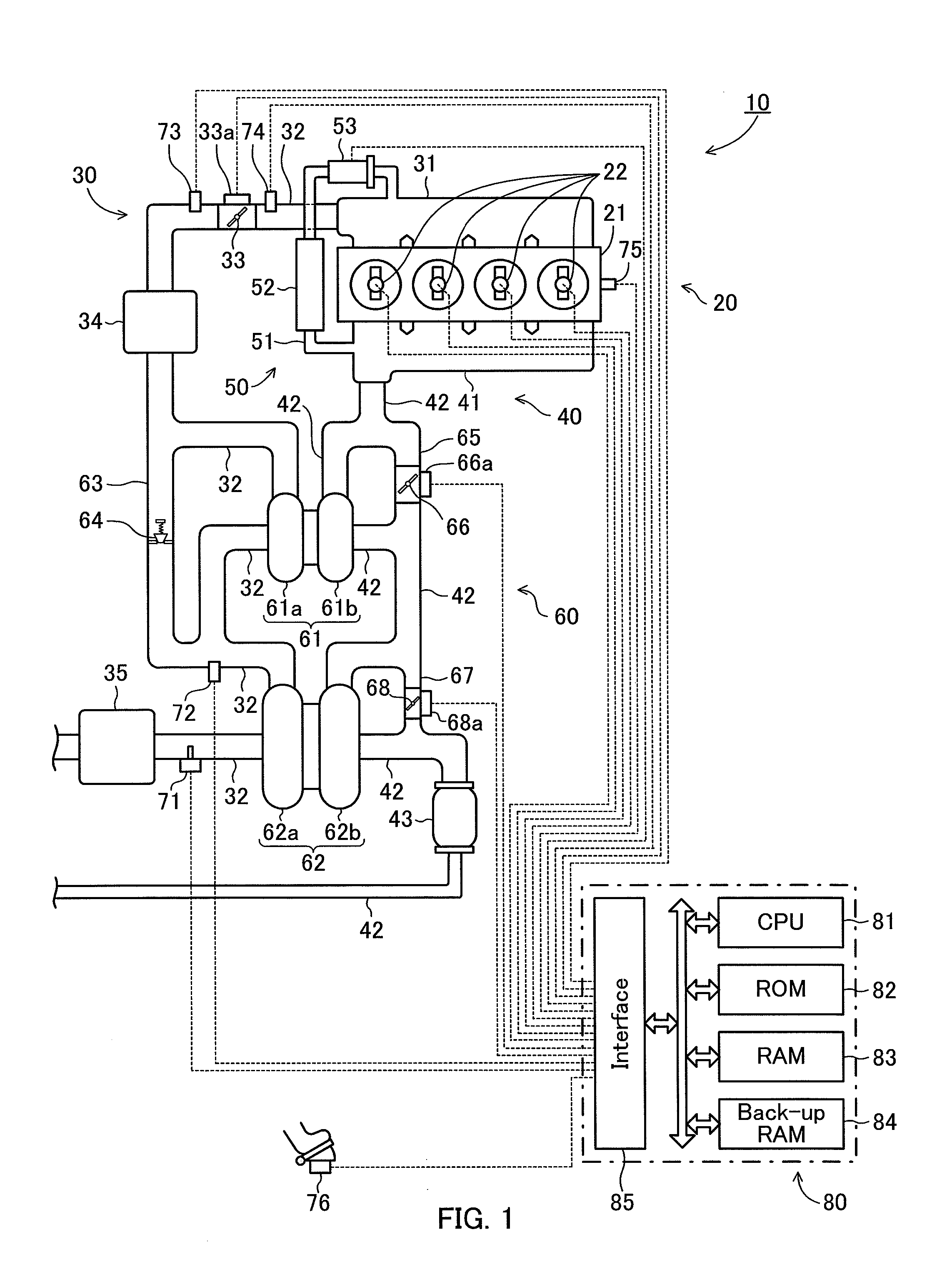
[0109]FIG. 1 shows a schematic configuration of a system including an internal combustion engine 10 to which an apparatus for determining an abnormality of a control valve according to a first embodiment of the present invention (hereinafter, this apparatus will be referred to as “a first apparatus”) is applied. The engine 10 is a four cylinder diesel engine.

[0110]The engine 10 comprises: an engine main body 20 including a fuel supply system, an intake system 30 for introducing an air into the engine main body 20; an exhaust system 40 for emitting an exhaust gas from the engine main body 20 to the outside; an EGR apparatus 50 for recirculating the exhaust gas to a side of the intake system 30; and supercharging apparatus 60 for compressing an air introduced into the engine main body 20 by being driven by an energy of the exhaust gas.

[0111]The engine main body 20 comprises a cylinder head 21 with which the intake system 30 and the exhaust system 40 are connected. Th...

second embodiment

A Second Embodiment

[0295]Next will be described an apparatus for determining an abnormality of a control valve according to a second embodiment of the present invention (hereinafter, this apparatus will be referred to as “a second apparatus”) is applied.

[0296]The second apparatus is applied to an internal combustion engine similar to the internal combustion engine 10 to which the first apparatus is applied.

[0297]The second apparatus is different from the first apparatus only in the following points.

[0298]The second apparatus send an instruction signal for forcibly changing the opening degree of the exhaust gas changeover valve 66 to the exhaust gas changeover valve actuator 66a, if a predetermined abnormality determining condition is satisfied when it is determined that “either one of the exhaust gas changeover valve 66 and the intake air changeover valve 64 is abnormal” in the first apparatus (refer to step 1026 in FIG. 10, step 1105 and step 1125 in FIG. 11). Subsequently, the sec...


PUM


Abstract

The present invention is applied to an internal combustion engine comprising a first supercharger 61, a second supercharger 62, a first control valve 66 for controlling a supply of an exhaust gas to the first supercharger, and a second control valve 64 for controlling a supply of an air to the first supercharger, and provides to an apparatus for determining an abnormality of a control valve which can determine abnormality of the first control valve and the second control valve. The apparatus for determining an abnormality of a control valve determines abnormality of a control valve when a supercharging pressure is smaller than a predetermined referential supercharging pressure by a predetermined value or more. The apparatus for determining an abnormality of a control valve determines that the first control valve is abnormal and the second control valve is normal if a pressure of an air at a downstream side of a compressor of the first supercharger is larger than a pressure of an air at an upstream side of the compressor by a predetermined value or more. In the meantime, the apparatus for determining an abnormality of a control valve determines that either one of the first control valve and the second control valve is abnormal if the pressure of the air at a downstream side of the compressor of the first supercharger is not larger than the pressure of the air at an upstream side of the compressor by a predetermined value or more.

Description

TECHNICAL FIELD[0001]The present invention relates to an apparatus for determining an abnormality of a control valve, applied to an internal combustion engine having a plurality of superchargers (turbocharger) and a plurality of control valves for controlling the plurality of superchargers.BACKGROUND ART[0002]A conventionally known supercharger (exhaust gas turbine type supercharger) comprises a turbine which is disposed in an exhaust gas passage of an internal combustion engine and is driven by energy of an exhaust gas, and a compressor which is disposed in an intake air passage of the engine and is driven by the driven turbine. Accordingly, an air introduced into the compressor is compressed by the compressor, and thereafter the air is discharged toward combustion chambers. That is, a supercharging is performed.[0003]It is well known that the supercharger can substantially compress an air introduced into the compressor, when a flow rate of the air is within a range from a predeter...

Claims


Application Information

Patent Timeline
IPC IPC(8): G01M13/02
CPCF02B37/013F02B37/16F02B37/18F02B39/16F02B37/004F02D2200/0406Y02T10/40Y02T10/144F02D41/221Y02T10/12
Inventor IBUKI, TAKUTOMITA, TETSUJIHIROSAWA, YOSHIHISA
Owner TOYOTA JIDOSHA KK
Features
  • Generate Ideas
  • Intellectual Property
  • Life Sciences
  • Materials
  • Tech Scout
  • Unparalleled Data Quality
  • Higher Quality Content
  • 60% Fewer Hallucinations
Learn More