
Frame for solar module

a solar module and frame technology, applied in the field of solar modules, can solve the problems of high cost of manufacturing devices capable of producing significant amounts of photovoltaic energy and limited solar energy use, and achieve the effect of increasing the bending strength of the frame and the thickness of the metal sh

Inactive Publication Date: 2011-06-30
DU PONT APOLLO
View PDF16 Cites 21 Cited by
  • Summary
  • Abstract
  • Description
  • Claims
  • Application Information

AI Technical Summary

Benefits of technology

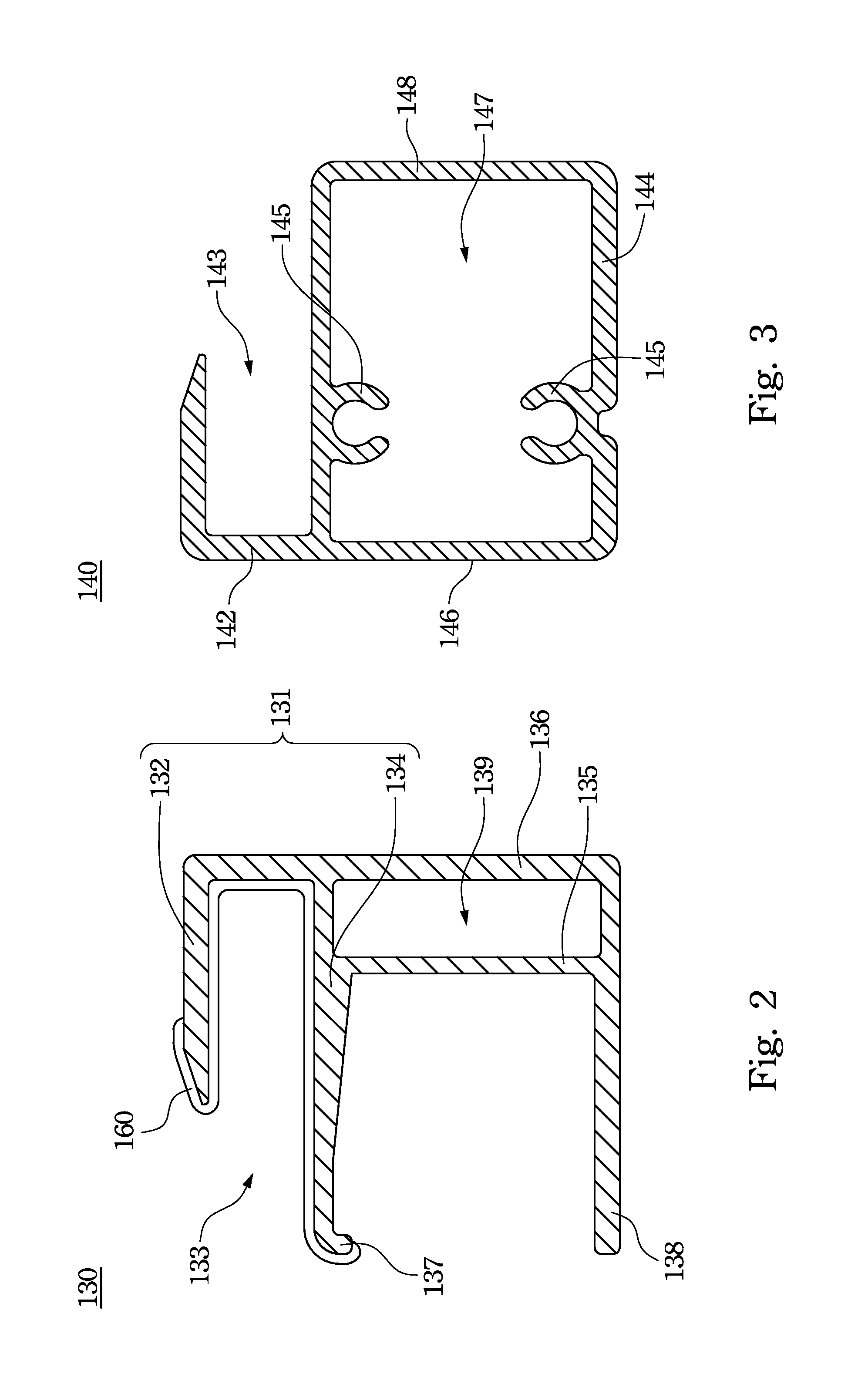
[0010]The beams of the first fastening members and the second fastening members of the invention could highly increase the bending strength of the frame for the solar module, so that the thickness of the metal sheet of the first fastening members and the second fastening members can be reduced. The first fastening members and the second fastening members are fixed by screws, thereby the first fastening members and the second fastening members are fixed firmly and better positioned. The support portion, the base portion, the connecting portion and the beam of each first and second fastening member are made integrated. The first fastening members and the second fastening members are made of metal, which can provide a grounding interface to the solar panel.

Problems solved by technology

Solar energy use has been limited in the past to special applications due in part to the high cost of manufacturing devices capable of producing significant amounts of photovoltaic energy.

Method used


Image

  • Frame for solar module
  • Frame for solar module
  • Frame for solar module

Examples


Embodiment Construction

[0018]Reference will now be made in detail to the present embodiments of the invention, examples of which are illustrated in the accompanying drawings. Wherever possible, the same reference numbers are used in the drawings and the description to refer to the same or like parts.

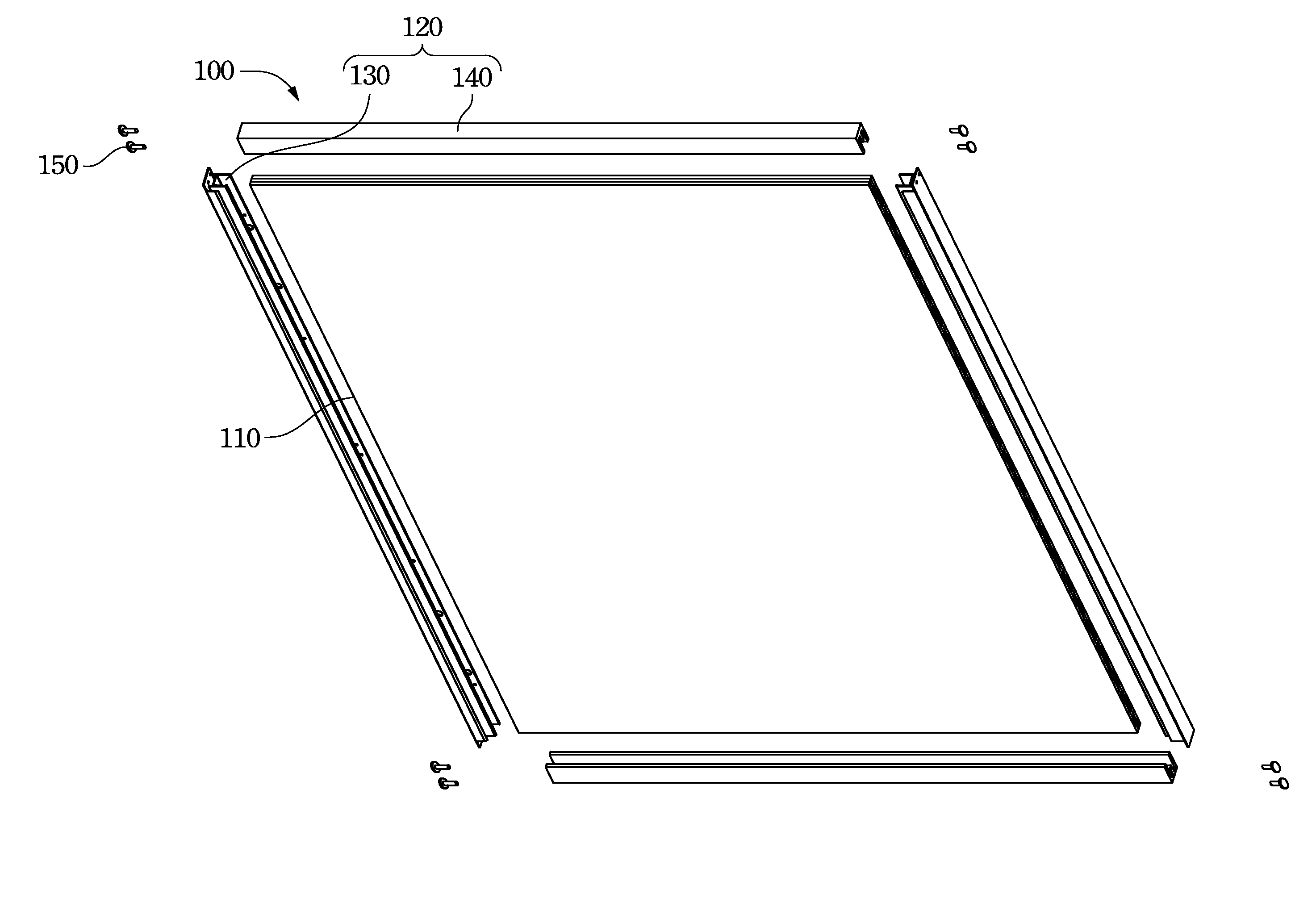
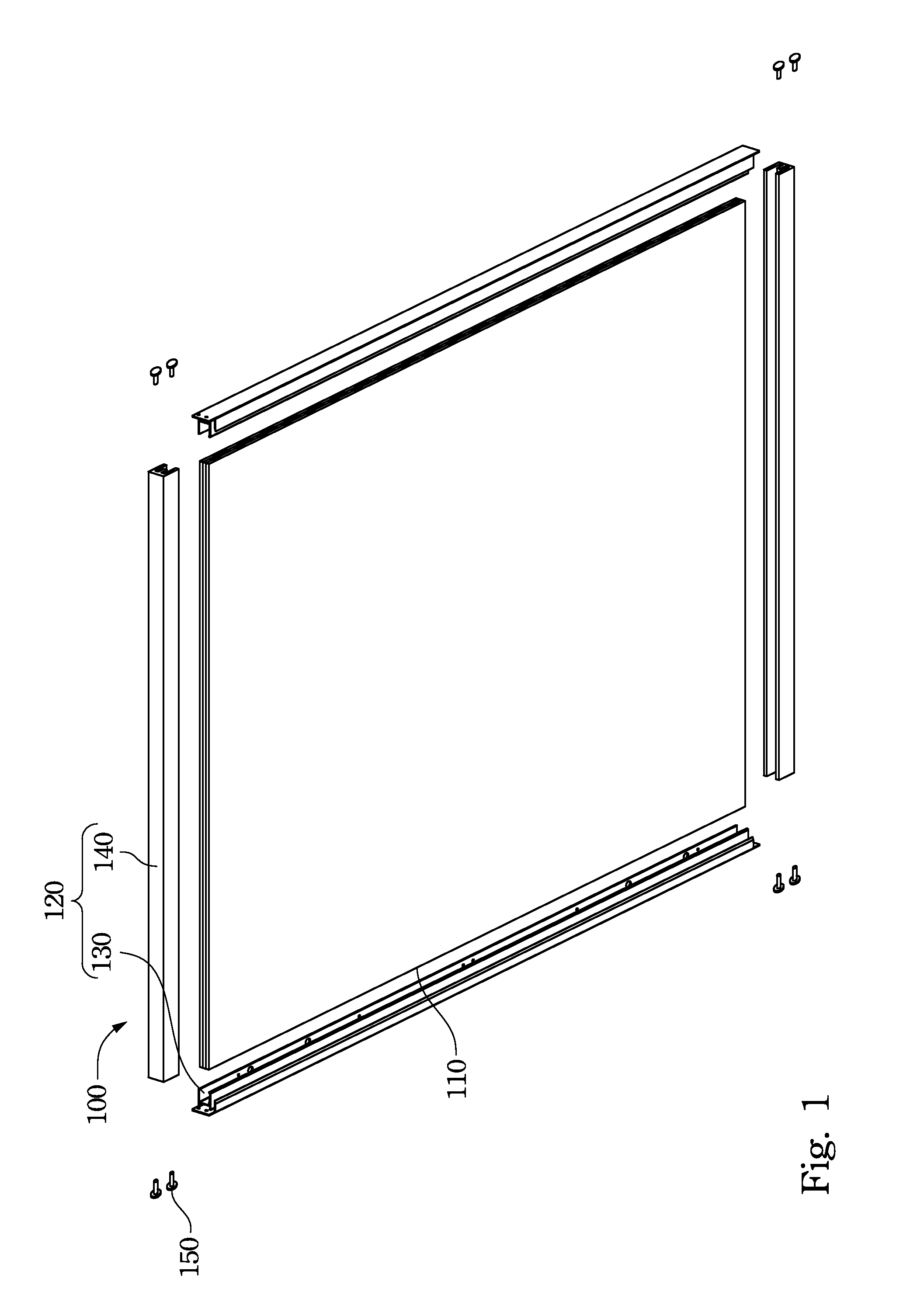
[0019]Refer to FIG. 1. FIG. 1 is a schematic diagram of an embodiment of a solar module utilizing the frame of the invention. The solar module 100 includes a solar panel 110 and a frame 120 to fix the solar panel 110. The solar panel 110 is a rectangle panel. The frame 120 includes plural fastening members encircled the solar panel 110 and coupled to each other to fix the solar panel 110 within. The frame 120 has two first fastening members 130 disposed at two opposite sides of the solar panel 110. The frame 120 has two second fastening members 140 disposed at other two opposite sides of the solar panel 110. The solar module 100 further includes plural screws 150 to screw the first fastening members 130 to the...


PUM


Abstract

A frame for solar module to fix a solar panel within is disclosed. The frame for solar panel includes two first fastening members arranged at two opposite sides of the solar panel, two second fastening members arranged at another two opposite sides of the solar panel, and plural screws to screw the first fastening members and the second fastening members. Each first fastening member and each second fastening member includes a supporting portion for supporting the solar panel, a base portion, a connecting portion for connecting the supporting portion and the base portion, and a beam disposed between the supporting portion and the base portion.

Description

RELATED APPLICATIONS[0001]This application claims priority to U.S. Provisional Application Ser. No. 61 / 291,403, filed Dec. 31, 2009, which is herein incorporated by reference.BACKGROUND[0002]1. Field of Invention[0003]The present invention relates to a solar module. More particularly, the present invention relates to a frame for solar module.[0004]2. Description of Related Art[0005]The increasing scarcity and the realization of the ecological and safety problems associated with non-renewable energy resources such as coal, petroleum and uranium, have made it essential that increased use be made of alternate non-depletable energy resources such as solar energy. Solar energy use has been limited in the past to special applications due in part to the high cost of manufacturing devices capable of producing significant amounts of photovoltaic energy. The improvement in manufacturing technology for fabricating the solar panel in mass production has greatly promoted the use of solar energy....

Claims


Application Information

Patent Timeline
IPC IPC(8): F24J2/46
CPCF24J2/5211F24J2002/5215H02S30/10Y02E10/47F24J2002/522F24S2025/804F24S25/20F24S2025/801Y02E10/50
Inventor LI, SZU-HANTSENG, HUNG-MING
Owner DU PONT APOLLO
Learn More