Method and arrangement in a pneumatic material conveying system

a conveying system and pneumatic technology, applied in the direction of water supply installation, drawing-off water installation, refuse gathering, etc., can solve the problems of increasing the energy consumption of the system, blocking the outlet aperture affecting the operation of the supply tank, so as to achieve efficient, simple and functional structure, and fast and effective draining of the supply tank

Inactive Publication Date: 2011-06-30
MARICAP OY
View PDF2 Cites 10 Cited by
  • Summary
  • Abstract
  • Description
  • Claims
  • Application Information

AI Technical Summary

Benefits of technology

[0010]The solution according to the invention has several remarkable advantages. By means of the invention, there is achieved a fast and effective draining of the supply tank to a conveyor pipe. By means of the method and arrangement according to the invention, makeup air can be advantageously conducted in the vicinity of the outlet aperture, so that it affects the material, such as waste material, as effectively as possible. At the same time, however, the blocking of the supply tank outlet aperture can be avoided, which means that the functions of the material conveying system continue in good order. By conducting the material by means of a wall element that can be shifted between a first position and a second position, there is achieved an efficient, simple and functional structure for realizing the method. When the material is conducted on an inclined bottom part towards the outlet aperture, it is easier to set the material in motion, and thus the energy demand in the arrangement can in part be reduced. When the wall element is arranged as a pipe element, there is achieved an efficient arrangement, particularly as a wall element to be used in connection with the feed chute. By arranging the wall element actuators to be used in connection with the outlet valve actuators, there is achieved a cost-effective solution. When separate actuators are provided for the wall element, there are obtained more versatile possibilities for moving the wall element, at least with respect to opening and closing the outlet valve. By opening the outlet valve before the wall element is shifted from the first position to the second position, there is created a powerful flow to a conveyor pipe, so that the shifting of the wall element releases material to a conveying flow. This serves as a propelling force when setting the conveyed material in motion. By feeding the makeup air particularly in the portion left between the lower part of the wall element and the outlet aperture, there is achieved a good boost effect in the material to be conveyed. According to the invention, there can be used material supply tanks, which are the feed points of waste material, such as waste bins or refuse chutes. The method and arrangement according to the invention are particularly well suited to be used in connection with systems for conveying waste material, such as waste material arranged in bags.

Problems solved by technology

When the connection from the supply tank to the conveyor pipe is opened, the material packed in the vicinity of the outlet aperture may block the outlet aperture or prevent the access of makeup air from the supply tank to a conveyor pipe.
This in turn increases the energy consumption in the system.
The tightly packed waste material may in part obstruct the opening of the valve.
On the other hand, it may become difficult to set the supplied material in motion at the lower portion of the feed chute.

Method used


Image

  • Method and arrangement in a pneumatic material conveying system
  • Method and arrangement in a pneumatic material conveying system
  • Method and arrangement in a pneumatic material conveying system

Examples


first embodiment

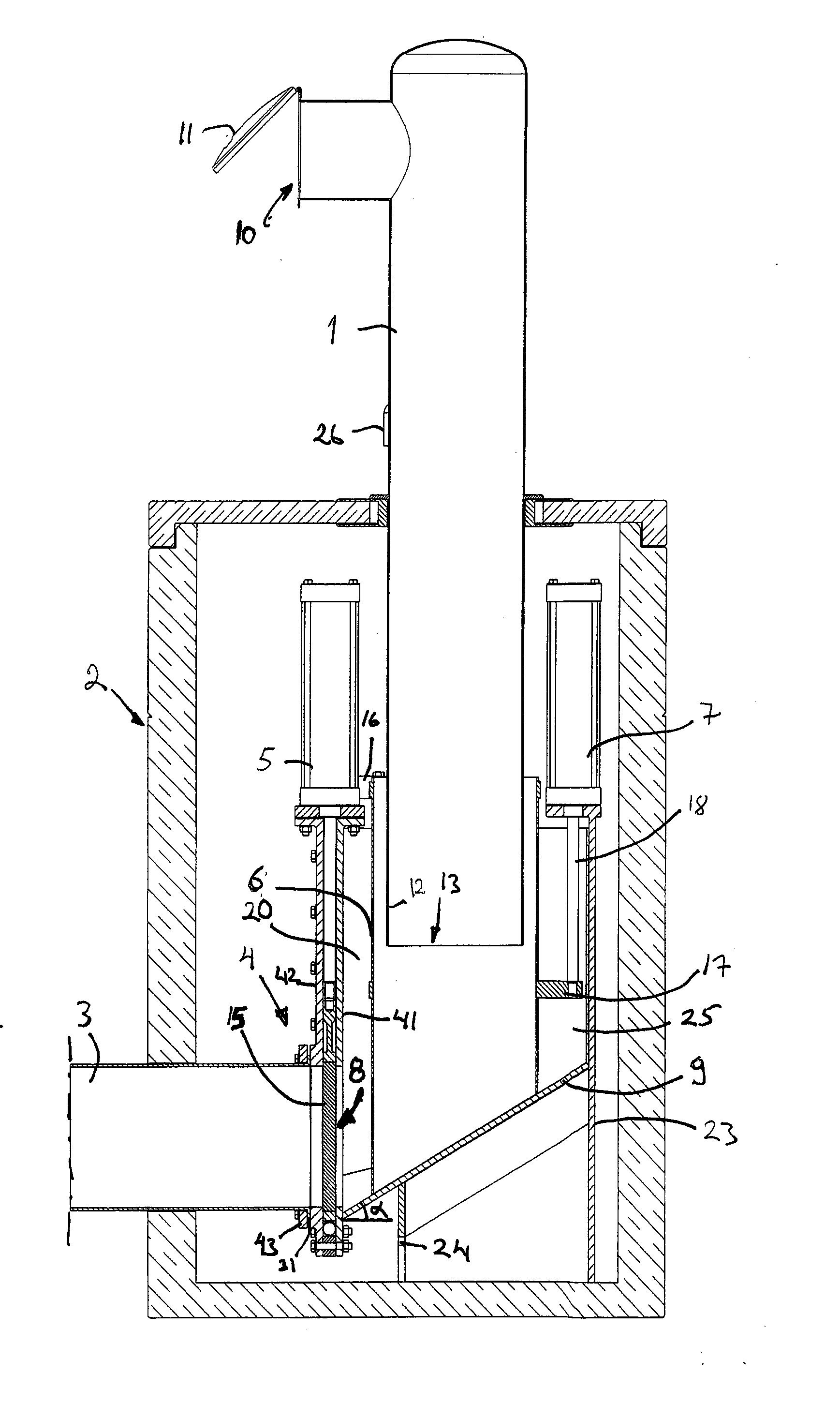
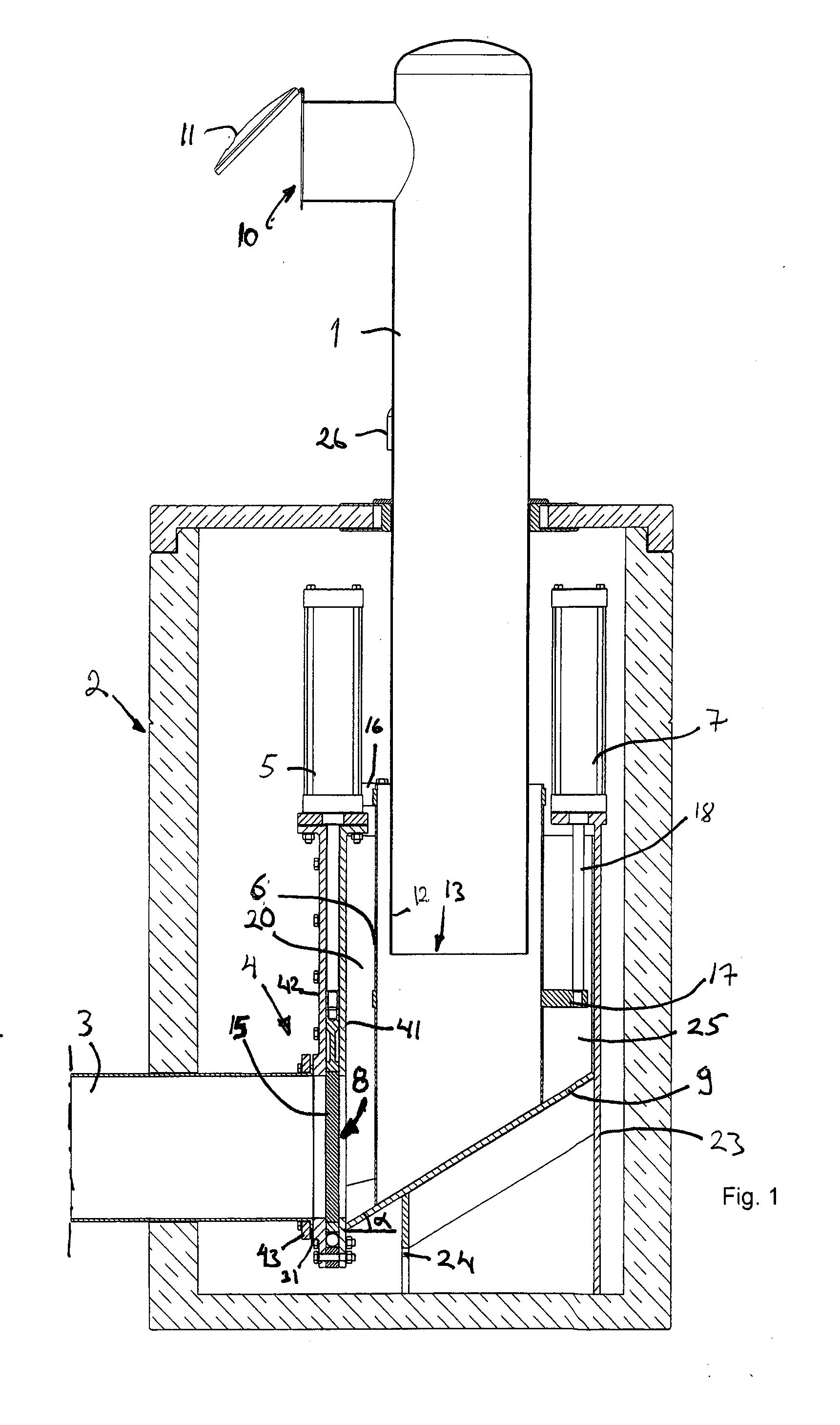
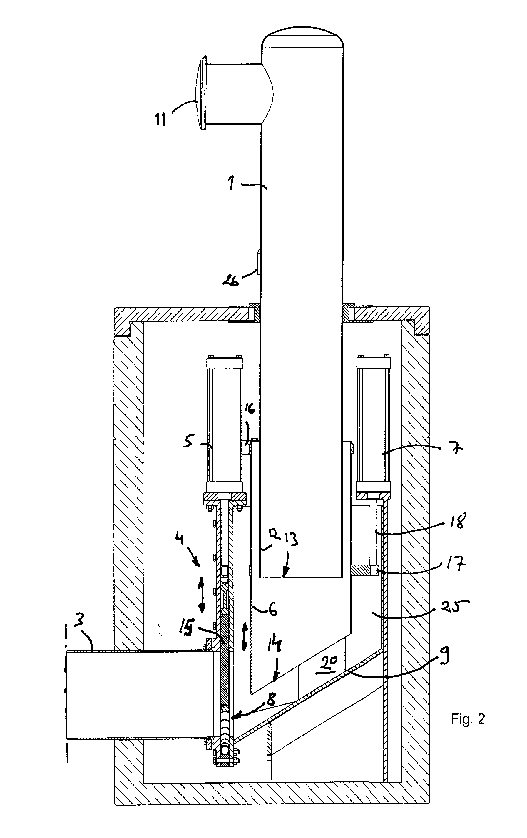
[0017]FIGS. 1-3 and 5 illustrate a supply tank 2 connected to the feed chute 1 in a material conveying system according to the invention. The supply tank 2 comprises a material space 20, which is connected to a conveyor pipe 3. In between the conveyor pipe 3 and the material space 20 of the supply tank 2, there is an outlet valve 4, which is driven by an actuator 5. The material space 20 of the supply tank is defined by walls 25. At least one feed chute 1 is provided in the material space via the upper portion of the material space 20, through which chute, material is conducted to the material space. In the feed chute, there is arranged at least one feed aperture 10, through which material is fed to the feed chute. In the embodiment illustrated in the drawings, a hatch 11 is provided in connection with the feed aperture. In the lower portion of the material space 20 of the supply tank 2, there is an outlet 8, through which material is transferred from the supply tank to the conveyor...

third embodiment

[0025] the wall element 6 is shifted from the first position to the second position at the same time as the outlet valve 4 is opened. Now the valve actuators can also be utilized for shifting the wall element. By using for instance connecting elements 16, 19, 21, the motion generated by the actuator 5 can be connected to the wall element.

[0026]According to a preferred embodiment, the material in the tank space 20 is guided towards the outlet aperture 8. Now there is achieved an effective transfer of the material from the tank space 20 to the conveyor pipe. By using an inclined bottom element 9, there is obtained an effective start for the material, as the own mass of the conveyed material can be made use of.

[0027]According to a preferred embodiment, the wall element 6 is a pipe element. In the embodiments of the drawings, the pipe element 6 is at least partly fitted around the lower portion of the feed chute 1. The material to be supplied is conducted in that part of the material sp...


PUM


Abstract

A method for draining the tank space (20) of a supply tank or feed chute in a pneumatic material conveying system, such as a waste conveying system, of material, such as waste material, in which method the tank space (20) is drained to a conveyor pipe (3) by opening an outlet valve (4), so that the underpressure prevailing in the conveyor pipe, together with the ambient pressure prevailing in the supply tank transfers material from the supply tank to the conveyor pipe (3). In the method, in the supply tank, a wall element (6) positioned at a distance from the outlet aperture (8) of the supply tank and / or from the outlet valve (4), which wall element (6) is arranged to move between at least two positions, i.e. a first position, where the wall element (6) restricts the access of material to the vicinity of the supply tank outlet aperture (8), and a second position, where the wall element (6) does not essentially restrict the access of material to the vicinity of the supply tank outlet aperture (8), is shifted from the first position to the second position. The invention also relates to an arrangement.

Description

BACKGROUND OF INVENTION[0001]The invention relates to a method according to the preamble of claim 1.[0002]The invention also relates to an arrangement according to claim 13.[0003]The invention relates generally to pneumatic conveying systems, such as vacuum conveying systems, particularly to collecting and conveying waste, for instance household waste.[0004]There are known systems where waste is conveyed in a piping by means of suction. In these, waste is conveyed by suction for long distances in the piping. Typical for them is that a vacuum apparatus is used for achieving a pressure difference, in which apparatus underpressure in the conveyor pipe is provided with vacuum generators, such as vacuum pumps or ejector equipment. In the conveyor pipe, there is typically arranged at least one valve element, and by opening and closing said valve element, make-up air coming in the conveyor pipe is regulated. In the systems, at the material feed end there are used supply tanks or feed chute...

Claims


Application Information

Patent Timeline
Patent Type & Authority Applications(United States)
IPC IPC(8): B65G51/02B65G53/04
CPCB65F5/005Y10T137/0402Y10T137/4245B65G53/4691B65F5/00B09B5/00
Inventor SUNDHOLM, GORAN
Owner MARICAP OY
Why Eureka
Try Eureka