
Multi-output engine welder supplying full electrical power capacity to a single welding output

a multi-output, welding output technology, applied in welding equipment, manufacturing tools, electric heating, etc., can solve the problems of high cost of switches of this type, prone to failure, and mechanical switches having to be sized

Active Publication Date: 2011-06-30
LINCOLN GLOBAL INC
View PDF4 Cites 25 Cited by
  • Summary
  • Abstract
  • Description
  • Claims
  • Application Information

AI Technical Summary

Benefits of technology

The present invention is an engine welder with a single rotor and stator that can distribute electrical power to various welding windings and auxiliary windings. The engine welder provides sufficient current to fully saturate the generator magnetics and allows for independent control of welding outputs on the stator side. The invention also provides means for supplying the full power capacity of the engine welder to a single stator welding winding and distributing the power capacity between welding windings and auxiliary windings of the stator. These features improve the efficiency and flexibility of the engine welder.

Problems solved by technology

However, such mechanical switches have to be sized to switch and carry high currents.
Switches of this type are costly and prone to failure.

Method used


Image

  • Multi-output engine welder supplying full electrical power capacity to a single welding output
  • Multi-output engine welder supplying full electrical power capacity to a single welding output
  • Multi-output engine welder supplying full electrical power capacity to a single welding output

Examples


Embodiment Construction

U.S. Pat. No. 5,166,567 to Kneisley et al. is incorporated herein by reference in its entirety as background information and supporting information related to engine welders. The term “welding winding” as used herein can refer to a single conductive coil winding (e.g., a copper coil winding) or a set of conductive coil windings (e.g., a three-phase Y-winding, a three-phase delta-winding, or a star-winding) dedicated to a single welding output of an engine welder. Similarly, the term “auxiliary winding” as used herein can refer to a single conductive coil winding (e.g., a copper coil winding) or a set of conductive coil windings (e.g., a three-phase Y-winding, a three-phase delta-winding, or a star-winding) dedicated to a single auxiliary power output of an engine welder.

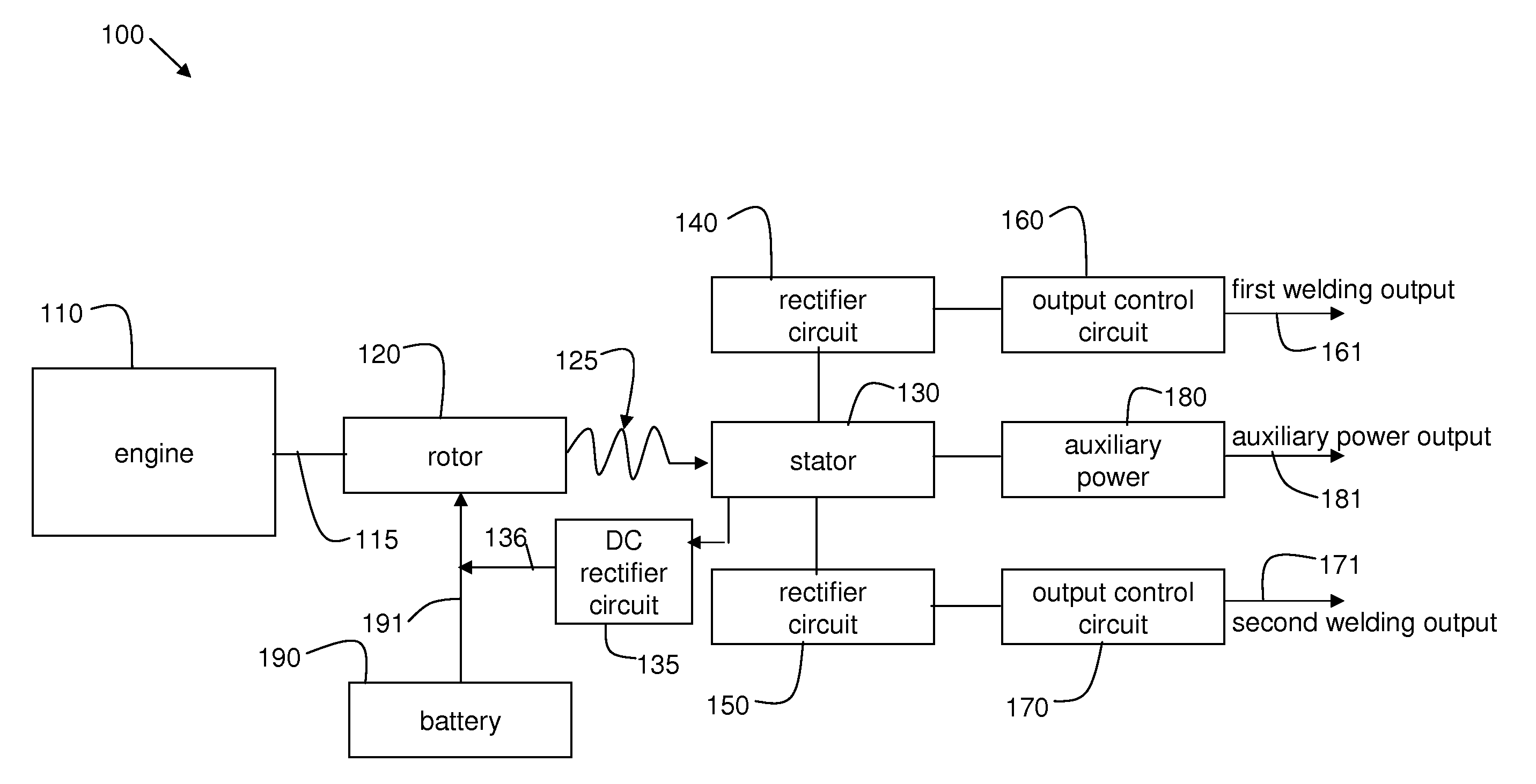
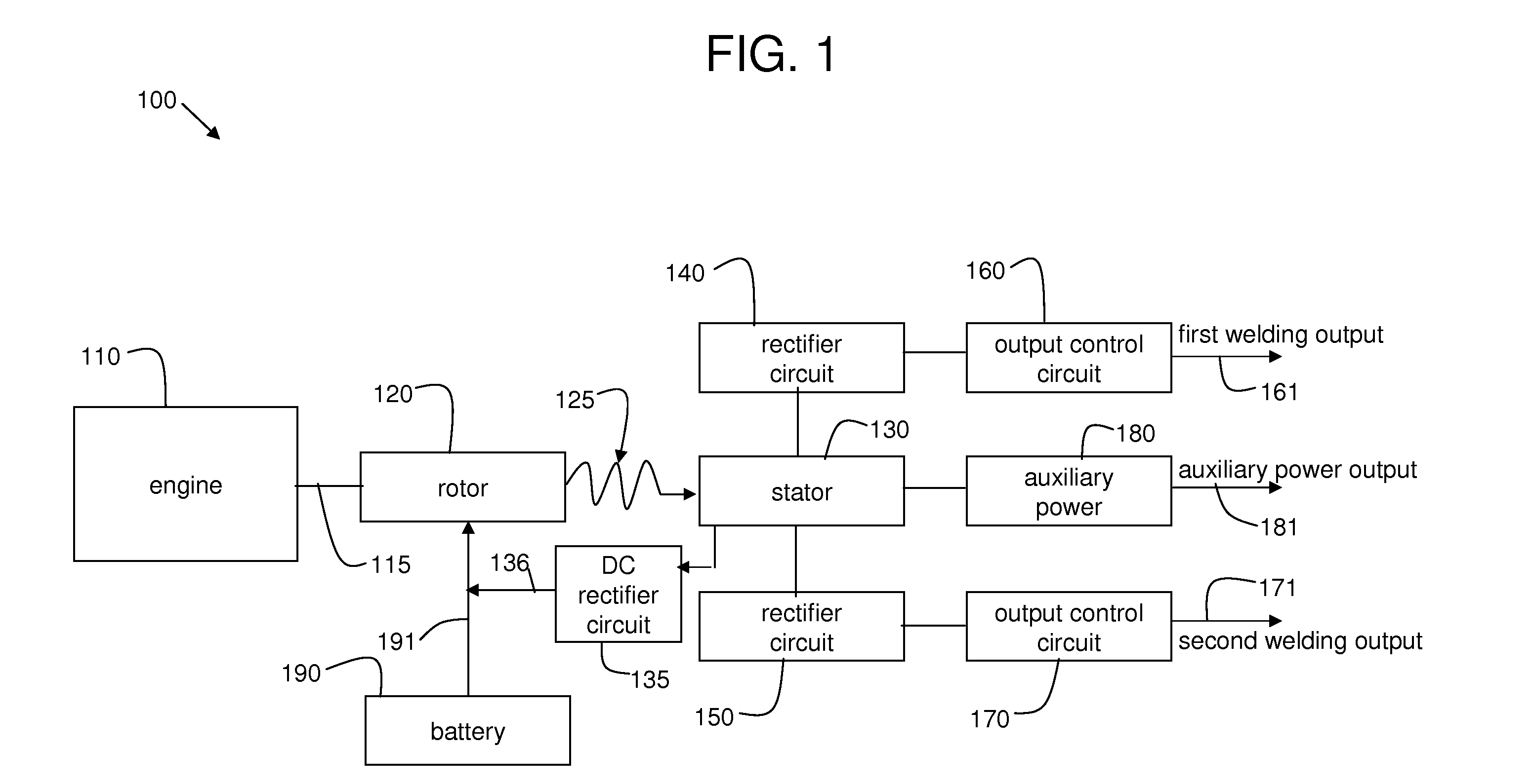
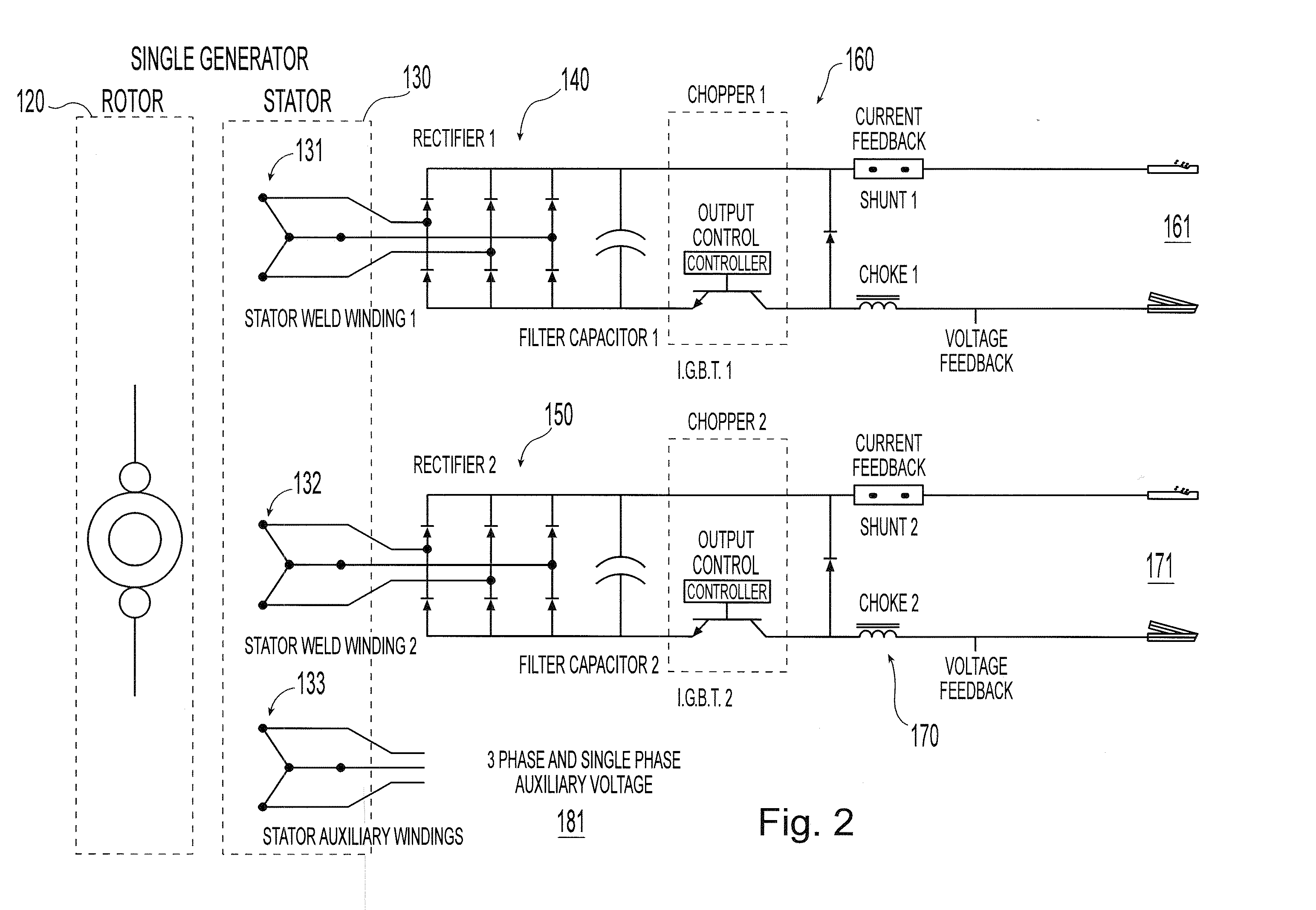
FIG. 1 illustrates a schematic block diagram of an example embodiment of an engine welder 100. FIG. 2 illustrates a diagram of a portion of the engine welder 100 of FIG. 1, in accordance with an example embodiment. T...


PUM

PropertyMeasurementUnit
poweraaaaaaaaaa
electrical power capacityaaaaaaaaaa
single phaseaaaaaaaaaa

Abstract

An engine welder having a single rotor and a single stator, and methods of distributing electrical power capacity of the engine welder to various welding windings and auxiliary windings of the engine welder. The single rotor is driven at saturation current and independent control of the welding outputs is accomplished on the stator side of the engine welder. Means for supplying the full electrical power capacity of the engine welder to a single stator welding winding are provided. Furthermore, means for distributing the electrical power capacity of the engine welder between welding windings and / or auxiliary windings of the single stator are provided.

Description

TECHNICAL FIELDThe claimed invention relates to arc welders and, more particularly, to engine arc welders.BACKGROUNDA typical engine welder machine includes an internal combustion engine coupled to a generator where the mechanical energy provided by the internal combustion engine is converted to electrical energy by the generator. Traditionally, engine welders provide one or more welding outputs or channels for arc welding along with one or more auxiliary power outputs to support various types of power tools. As a result, one or more users may be able to use the same engine welder at the same time. For some engine welders that provide more than one welding output, users have had to combine the multiple welding outputs in parallel in order to access the full electrical power capacity of the engine welder for a single welding operation. Some engine welders have internal mechanical switches allowing two or more welding channels to be combined in parallel within the engine welder. Howev...

Claims


Application Information

Patent Timeline
Patent Type & Authority Applications(United States)
IPC IPC(8): B23K9/10
CPCB23K9/1068
Inventor FARAH, SAMIR F.MECKLER, ANDREU P.
Owner LINCOLN GLOBAL INC
Learn More