Tubeless light-emitting diode based lighting device

a technology of light-emitting diodes and lighting devices, which is applied in lighting and heating devices, lighting support devices, instruments, etc., can solve the problems of shortened lifespan, excessive power consumption, and shortened lifespan of users, so as to reduce the overall weight and size of lighting devices, reduce the amount of ferrous materials, and reduce power consumption

Inactive Publication Date: 2011-06-30
UNISTAR OPTO CORP
View PDF7 Cites 12 Cited by
  • Summary
  • Abstract
  • Description
  • Claims
  • Application Information

AI Technical Summary

Benefits of technology

[0015]The effectiveness of the tubeless LED based lighting device of the present invention is that a tubeless lighting device is composed of a base, an LED lighting module, a control circuit, and a shade, which greatly reduces the overall weight and size of a lighting device and also reduces the amount of ferrous material used and the number of contact points in the circuit thereof, so as to reduce power consumption, eliminate potential risk of environmental pollution, and extend the lifespan of the lighting device. Further, the risk of falling tube hurting users can be avoided to ensure operation safety and make the tubeless LED based lighting device applicable to various environments.

Problems solved by technology

The state-of-the-art fluorescent tubes of LED based power-saving lighting devices require a tube, which makes the known lighting devices heavy and bulky and consuming a large amount of ferrous material and adding a large number of contact points, leading to excessive power consumption, environmental pollution, and shortened lifespan.
Structural instability may occur between the known lighting tube and tube connectors, which often causes falling of the tube to hurt users and limits the applications of the lighting tubes in certain environments, where vibrations / quakes must be constrained.

Method used


Image

  • Tubeless light-emitting diode based lighting device
  • Tubeless light-emitting diode based lighting device
  • Tubeless light-emitting diode based lighting device

Examples


first embodiment

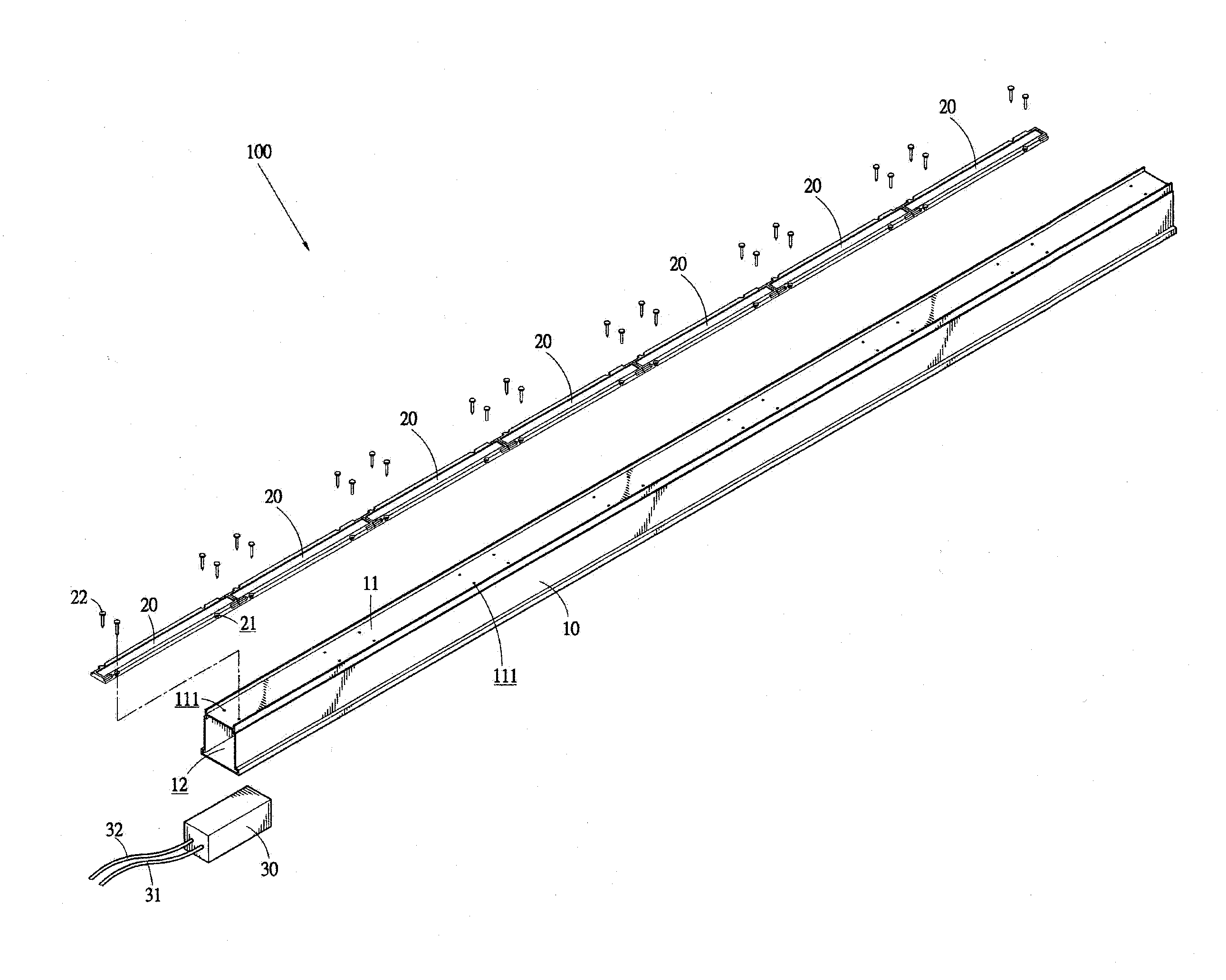
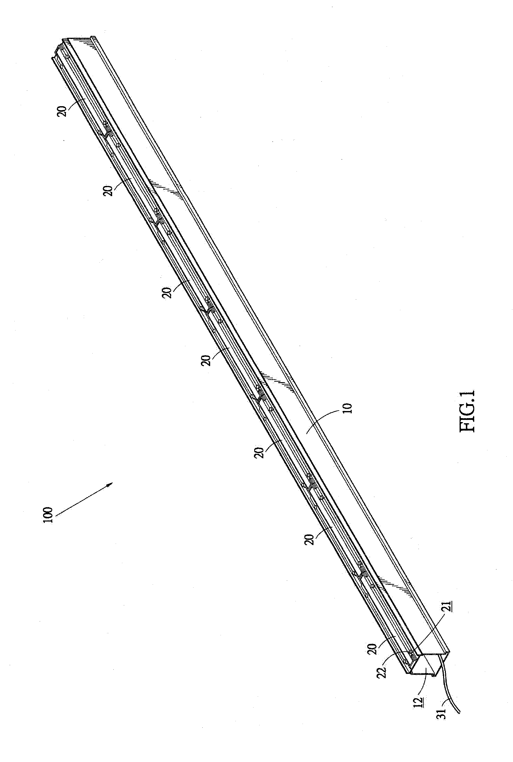
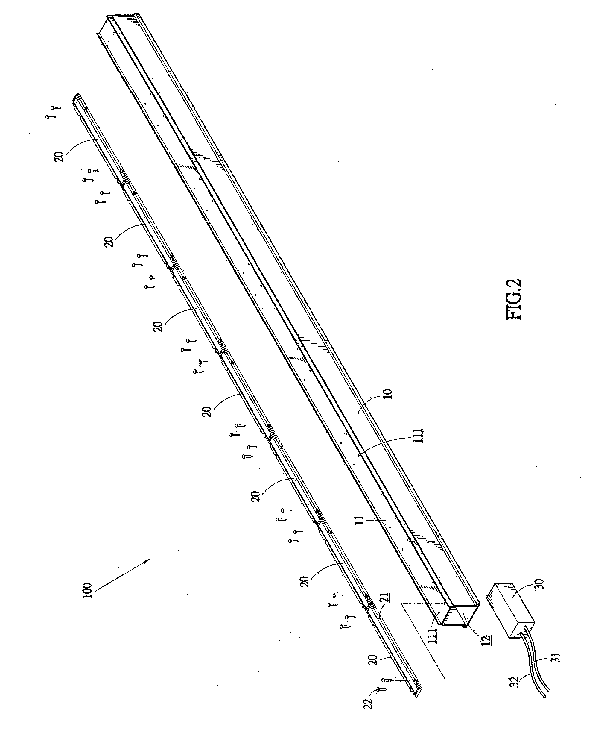
[0032]At least one LED lighting module 20 is provided and a single multi-dice packaged LED chip is taken as an example for the LED lighting module 20 in the The LED lighting module 20 has a surface forming a plurality of through holes 21 respectively corresponding to the inner-threaded holes 111 of the base 10 and respectively receiving threaded fasteners 22, such as screws or bolts, for connecting and fixing the LED lighting module 20 to the connection section 11 of the base 10, whereby the base 10, as a whole, serves heat dissipation for the LED lighting module 20.

[0033]At least one control circuit 30 is provided, having the functions of controlling ON / OFF switching of the LED(s) and conversion between alternate current (AC) and direct current (DC). The control circuit 30 is received and retained in the receiving channel 12 of the base 10. The control circuit 30 comprises least one power cable 31 and a control cable 32. The power cable 31 extends out of the receiving channel 12 o...

second embodiment

[0035]Referring to FIGS. 3 and 4, a tubeless LED based lighting device constructed in accordance with the present invention is shown, and is also designated with reference numeral 100. At least one shade 40 is coupled to the base 10. The shade 40 has inside edges forming at least one fitting rim 41 for fitting to and thus attaching to the top of the base 10 and covering outside the LED lighting module 20. The shade 40 also provides the function of adjustment of light projection for the surface light source of the LED lighting module 20. A pair of end caps 50 is attached to and seals opposite open ends between the shade 40 and the base 10. Each of the end caps 50 has a lower portion forming a plurality of connection tabs 51 and defines an opening 52. The connection tabs 51 are fit into the receiving channel 12 of the base 10, and one of end caps 50 allows the power cable 31 of the control circuit 30 to extend outward through the opening 52 thereof. The opening 52 of the end caps 50 i...

third embodiment

[0036]Referring to FIGS. 5 and 6, a tubeless LED based lighting device constructed in accordance with the present invention is shown and is also designated with reference numeral 100. At least one mounting element 13 is fit over and clamps a bottom of the base 10. The mounting element 13 forms at least one hole 131 that receives a fastener 131A to extend therethrough for mounting to a fixture, such as ceiling, whereby the base 10 is attached to the ceiling 200 to allow tubeless LED based lighting device 100 of the present invention to be applicable to ceiling lighting mounted to the ceiling 200.

[0037]The mounting of tubeless LED based lighting device 100 shown in FIGS. 5 and 6 to the ceiling 200 is not limited to use of a mounting element 13 that is fit over and clamps the base 10, and any other equivalent arrangements and structures are considered within the scope of the present invention.


PUM


Abstract

A tubeless light-emitting diode (LED) based lighting device includes at least one base, at least one LED lighting module, and at least one control circuit. The base includes a heat dissipation body. The LED lighting module is mounted to the base so that the base provides the LED lighting module with the functions of retention and heat dissipation. The control circuit is mounted to the base and is electrically connected to power wiring of the LED lighting module for ON/OFF switching of the LED lighting module and supplying of operation power. As such, a tubeless lighting device that emits light in a power saving manner and is constructed in a volume reduced manner is provided.

Description

BACKGROUND OF THE INVENTION[0001]1. Field of the Invention[0002]The present invention relates to a tubeless lighting device, and in particular to a light-emitting diode (LED) based lighting device that has a tubeless structure for indoor and outdoor applications for lighting and features environmental conservation, power saving, and volume reduction.[0003]2. The Related Arts[0004]Fluorescent lamps are well known for indoor and outdoor applications for lighting. A conventional fluorescent tube gives off light by applying electrical discharging and requires various components, including a tube mount, tube connectors, and a ballast (transformer) and a starter. This leads to the disadvantages of being heavy and bulky and requiring a large amount of ferrous material. Further, the fluorescent tube contains therein mercury, which is considered a server environmental pollutant. Thus, the fluorescent tube, once disposed of, often leads to pollution to the environment. Further, a number of co...

Claims


Application Information

Patent Timeline
Patent Type & Authority Applications(United States)
IPC IPC(8): H01J13/32H05B39/02H05B44/00
CPCF21S4/008F21V15/01F21V15/013F21V15/015F21V21/025F21Y2111/004F21V23/026F21V31/005F21V31/04F21Y2101/02F21Y2103/003F21V23/02F21S4/28F21Y2103/10F21Y2115/10F21Y2107/20H01L33/486H05B45/00
Inventor LIN, CHIN-LUNG
Owner UNISTAR OPTO CORP
Why Eureka
Try Eureka