Vehicular traffic control system

a technology for traffic control and vehicles, applied in traffic control systems, road vehicles traffic control, instruments, etc., to achieve the effect of increasing the cost to municipalities

Inactive Publication Date: 2011-06-30
ULMER GERALD
View PDF19 Cites 3 Cited by
  • Summary
  • Abstract
  • Description
  • Claims
  • Application Information

AI Technical Summary

Benefits of technology

[0012]The use of the traffic control system and traffic signals as described herein has several advantages. The traffic control system and traffic signals provide additional warning to the motorist by providing additional functionality to the signals, allowing the motorist to view the appropriate signal without obstruction. The traffic control system and traffic signals provide the additional safety benefits without significantly increasing the cost to municipalities associated with the installation of additional traffic signals.

Problems solved by technology

Certain problems confront a motorist when approaching a blind intersection or when approaching an intersection in which motorist vision is obstructed in a direction toward the traffic signal by a large tractor trailer truck or the like.

Method used


Image

  • Vehicular traffic control system
  • Vehicular traffic control system
  • Vehicular traffic control system

Examples


Embodiment Construction

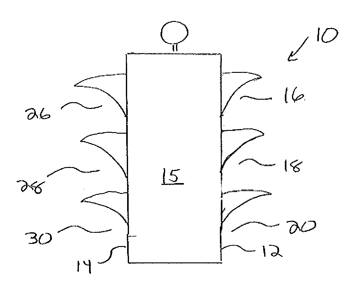
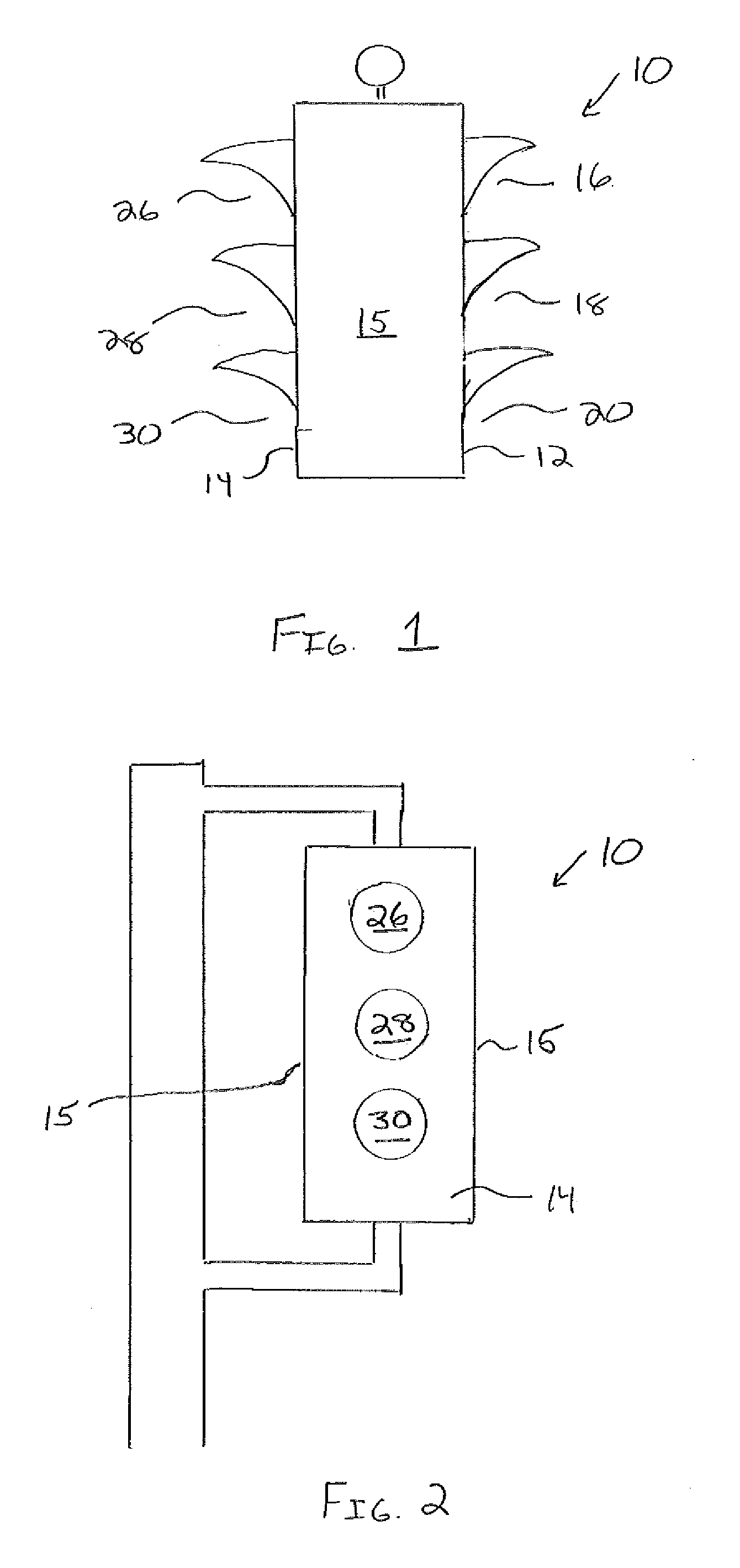
[0019]Referring to FIGS. 1 and 2, a traffic signal 10, according to the present invention, has a front or first face 12, an oppositely facing rear or second face 14, and side faces 15 which extend between the front face 12 and rear face 14. The front face 12 of the traffic signal 10 is positioned to face and control vehicular traffic in a first direction, which is generally referred to as the oncoming or opposing vehicular traffic for that respective traffic signal. As is generally known in the art, a red “STOP” signal 16 is located above a green “GO” signal 20 with a yellow or amber “WARNING” signal 18 located between the two. The significance or meaning of these signals are well known and will not be described here other than to state that yellow signal 18 will be illuminated when green signal 20 is turned off to indicate to an oncoming motorist that red signal 16 will soon be switched on. When red signal 16 is switched on, yellow signal 18 is switched off. Generally, the yellow s...


PUM


Abstract

A traffic control system and a traffic signal to increase traffic signal visibility. The traffic control system has a traffic signal with a first face and an oppositely facing second face. The first face has a first red light, a first amber light and a first green light. The first face is directed to and controls vehicles travelling in a first direction in a first lane of traffic. The second face has a second red light, a second amber light and a second green light. The second face is directed to and controls vehicles in a second direction in a second lane of traffic, the second direction is opposed to the first direction. The traffic signal is positioned over the first lane of traffic, whereby vehicles travelling in the second lane of traffic have an unobstructed view of the second face of the at least one first traffic signal.

Description

FIELD OF THE INVENTION[0001]The invention relates generally to a vehicular traffic control system and, more particularly, to a traffic control system in which the traffic signal is not obstructed from the vision of oncoming drivers.BACKGROUND OF THE INVENTION[0002]Traffic lights are positioned at road intersections, pedestrian crossings, and other locations to control competing flows of traffic. They are used at busy intersections to more evenly apportion delay to the various users and to assign the right of way to road users by the use of lights in standard colors (Red-Amber-Green). Traffic control systems and traffic light technology are constantly evolving with the aims of improving reliability, visibility, and efficiency of traffic flow.[0003]There are significant differences from place to place in how traffic lights are mounted or positioned so that they are visible to drivers. Depending upon the location, traffic lights may be mounted on poles situated on street corners, hung ...

Claims


Application Information

Patent Timeline
Patent Type & Authority Applications(United States)
IPC IPC(8): G08G1/095
CPCG08G1/095
Inventor ULMER, GERALD
Owner ULMER GERALD
Why Eureka
Try Eureka