Collimator lens unit, illuminating device, and projector

a technology of illumination device and lens, which is applied in the field of illumination device and projector, can solve the problems of achieve the effect of high light use efficiency and not reducing light use efficiency

Active Publication Date: 2011-06-30
SEIKO EPSON CORP
View PDF8 Cites 27 Cited by
  • Summary
  • Abstract
  • Description
  • Claims
  • Application Information

AI Technical Summary

Benefits of technology

[0052]According to this configuration, it is possible to provide a projector with a high light use efficiency in which the light use efficiency does not decrease due to the increase in ratio of the light applied at a large angle to the light applied to the illumination area.

Problems solved by technology

As a result, in a projector employing particularly a liquid crystal device having a micro lens built therein as an optical modulator, there is a problem in that the light use efficiency decreases due to the increase in ratio of the light applied at a large angle to the light applied to the illumination area.

Method used


Image

  • Collimator lens unit, illuminating device, and projector
  • Collimator lens unit, illuminating device, and projector
  • Collimator lens unit, illuminating device, and projector

Examples


first embodiment

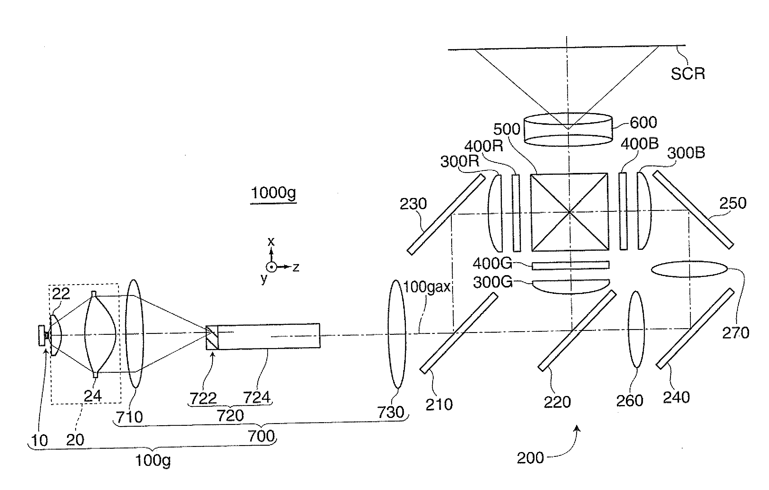
[0072]First, the configurations of a collimator lens unit 20, an illuminating device 100, and a projector 1000 according to a first embodiment of the invention will be described.

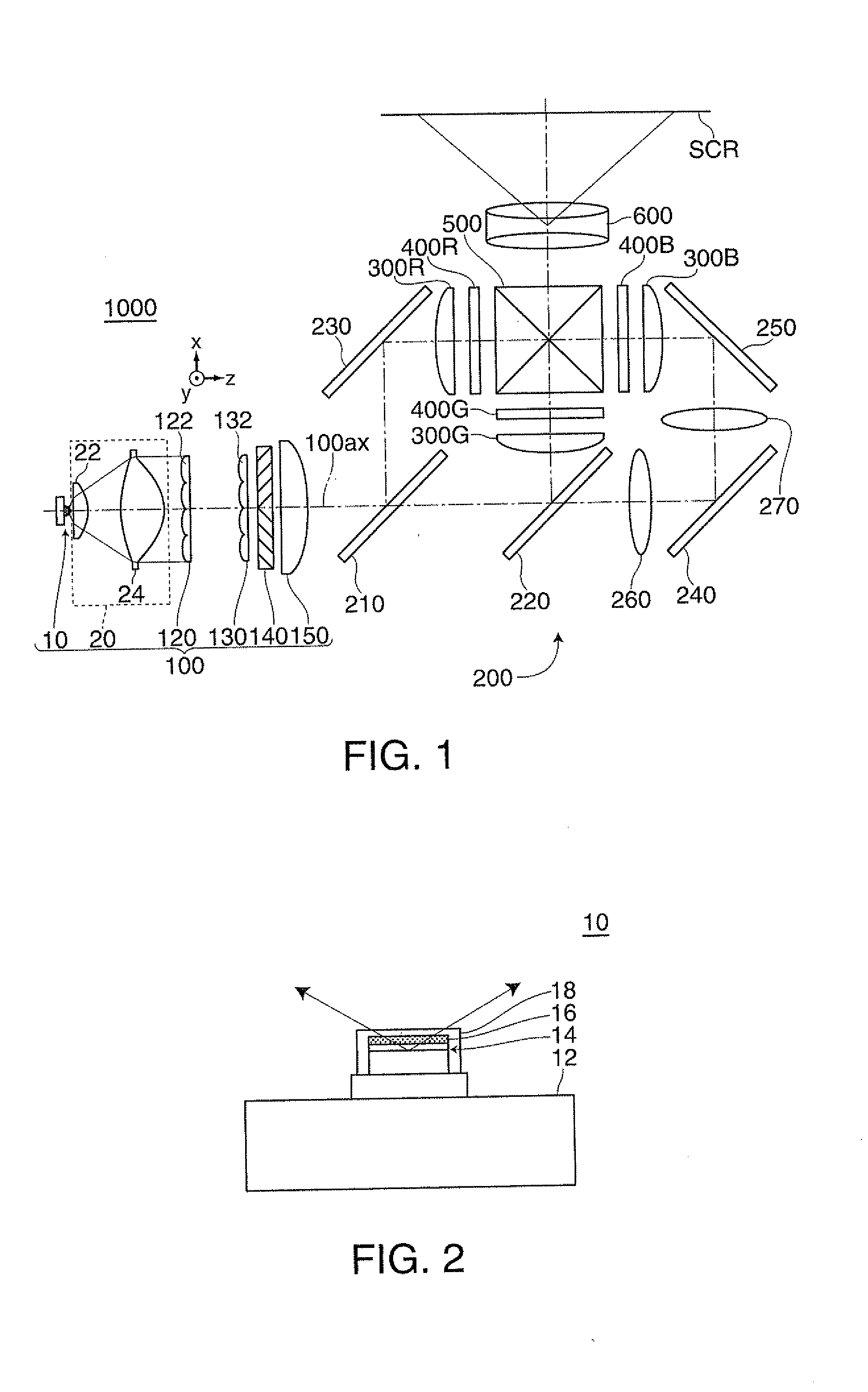
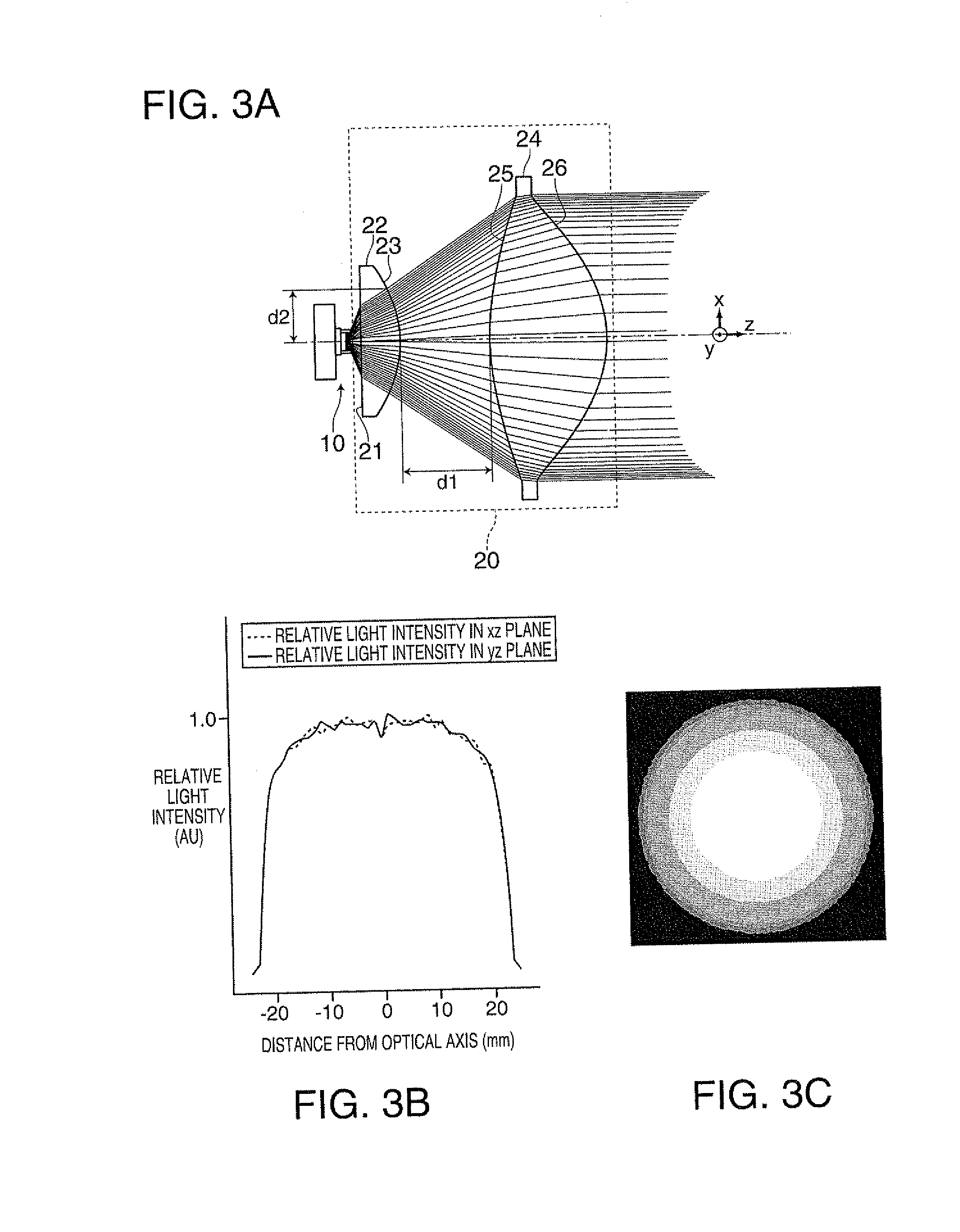
[0073]FIG. 1 is a plan view illustrating an optical system of the projector 1000 according to the first embodiment of the invention. FIG. 2 is a sectional view illustrating a solid-state light source unit 10 according to the first embodiment. FIGS. 3A to 3C are diagrams illustrating the collimator lens unit 20 according to the first embodiment. FIG. 3A illustrates a state where a beam of light emitted from the solid-state light source unit 10 is substantially collimated by the collimator lens unit 20, FIG. 3B is a graph illustrating a relative light intensity (relative luminous flux density) of a beam of light emitted from the collimator lens unit 20, and FIG. 3C illustrates an in-plane light intensity distribution (luminous flux density distribution) of the beam of light emitted from the collimator lens uni...

second embodiment

[0106]FIGS. 4A to 4C are diagrams illustrating the collimator lens unit 20a according to the second embodiment. FIG. 4A illustrates a state where a beam of light emitted from the solid-state light source unit 10 is substantially collimated by the collimator lens unit 20a, FIG. 4B is a graph illustrating a relative light intensity (relative luminous flux density) of a beam of light emitted from the collimator lens unit 20a, and FIG. 4C illustrates an in-plane light intensity distribution (luminous flux density distribution) of the beam of light emitted from the collimator lens unit 20a. The beam of light shown in FIG. 4A shows a state where the beam of light emitted from the solid-state light source unit 10 is substantially collimated by the collimator lens unit 20a, but does not reflect the luminous flux density. In FIG. 4B, the vertical axis represents the relative light intensity of the beam of light emitted from the collimator lens unit 20a, where the light intensity in an optica...

third embodiment

[0110]FIGS. 5A to 5C are diagrams illustrating the collimator lens unit 20b according to the third embodiment. FIG. 5A illustrates a state where a beam of light emitted from the solid-state light source unit 10 is substantially collimated by the collimator lens unit 20b, FIG. 5B is a graph illustrating a relative light intensity (relative luminous flux density) of a beam of light emitted from the collimator lens unit 20b, and FIG. 5C illustrates an in-plane light intensity distribution (luminous flux density distribution) of the beam of light emitted from the collimator lens unit 20b. The beam of light shown in FIG. 5A shows a state where the beam of light emitted from the solid-state light source unit 10 is substantially collimated by the collimator lens unit 20b, but does not reflect the luminous flux density. In FIG. 5B, the vertical axis represents the relative light intensity of the beam of light emitted from the collimator lens unit 20b, where the light intensity in an optical...


PUM


Abstract

A collimator lens unit includes at least two lenses and substantially collimates a beam of light emitted from a solid-state light source unit of a Lambert emission type, wherein at least two faces of incidence faces and emission faces of the lenses constituting the two lenses are aspheric faces, one front aspheric face located close to the solid-state light source unit has a function of changing a luminous flux density distribution of the beam of light emitted from the solid-state light source unit to a predetermined luminous flux density distribution in which the luminous flux density in the vicinity of an optical axis of the collimator lens unit is higher than the luminous flux density in a peripheral portion separated from the optical, the rear aspheric face farthest from the solid-state light source unit has a function of substantially collimating the beam of light.

Description

BACKGROUND[0001]1. Technical Field[0002]The present invention relates to a collimator lens unit, an illuminating device, and a projector.[0003]2. Related Art[0004]Hitherto, a collimator lens unit including a first lens suppressing a spread angle of a beam of light emitted from a solid-state light source unit and a second lens substantially collimating the beam of light from the first lens has been known (for example, see JP-A-2005-208571).[0005]Since the collimator lens unit substantially collimates the beam of light, the spread angle of which is suppressed by the first lens, by the use of the second lens, it is possible to efficiently substantially collimate the beam of light emitted from the solid-state light source unit.[0006]On the other hand, a projector employing a white solid-state light source unit including a solid-state light source emitting main exciting light and a fluorescent layer converting and emitting the main exciting light has been known (see JP-A-2005-274957).[00...

Claims


Application Information

Patent Timeline
Patent Type & Authority Applications(United States)
IPC IPC(8): G03B21/20G02B27/30F21V5/04F21V29/00
CPCG02B27/30G03B33/12G03B33/08G03B21/20
Inventor AKIYAMA, KOICHI
Owner SEIKO EPSON CORP
Why Eureka
Try Eureka