
Method and apparatus for controlling sleep mode in wireless communication networks

a wireless communication network and wireless communication technology, applied in climate sustainability, sustainable buildings, high-level techniques, etc., can solve the problems of high power consumption, significant factors affecting the overall performance of wireless communication systems, and power consumption of ms, so as to maximize power saving and prolong sleep duration

Active Publication Date: 2011-06-30
KOREA ADVANCED INST OF SCI & TECH
View PDF1 Cites 23 Cited by
  • Summary
  • Abstract
  • Description
  • Claims
  • Application Information

AI Technical Summary

Benefits of technology

[0015]The present invention has been conceived to solve the problems described above and it is, therefore, an object of the present invention to provide a method and an apparatus for maximizing power saving by lengthening sleep duration through adoption of the N-ary exponential sleep mode of a BS and an MS in the wireless communication network, where N is set to be equal to or greater than 2, and in particular, if N=2 then it corresponds to the conventional binary exponential sleep mode.

Problems solved by technology

Due to a limited battery life of a mobile station (hereinafter, referred to as “MS”), power consumption of the MS is one of the factors significantly affecting overall performance of the wireless communication systems.
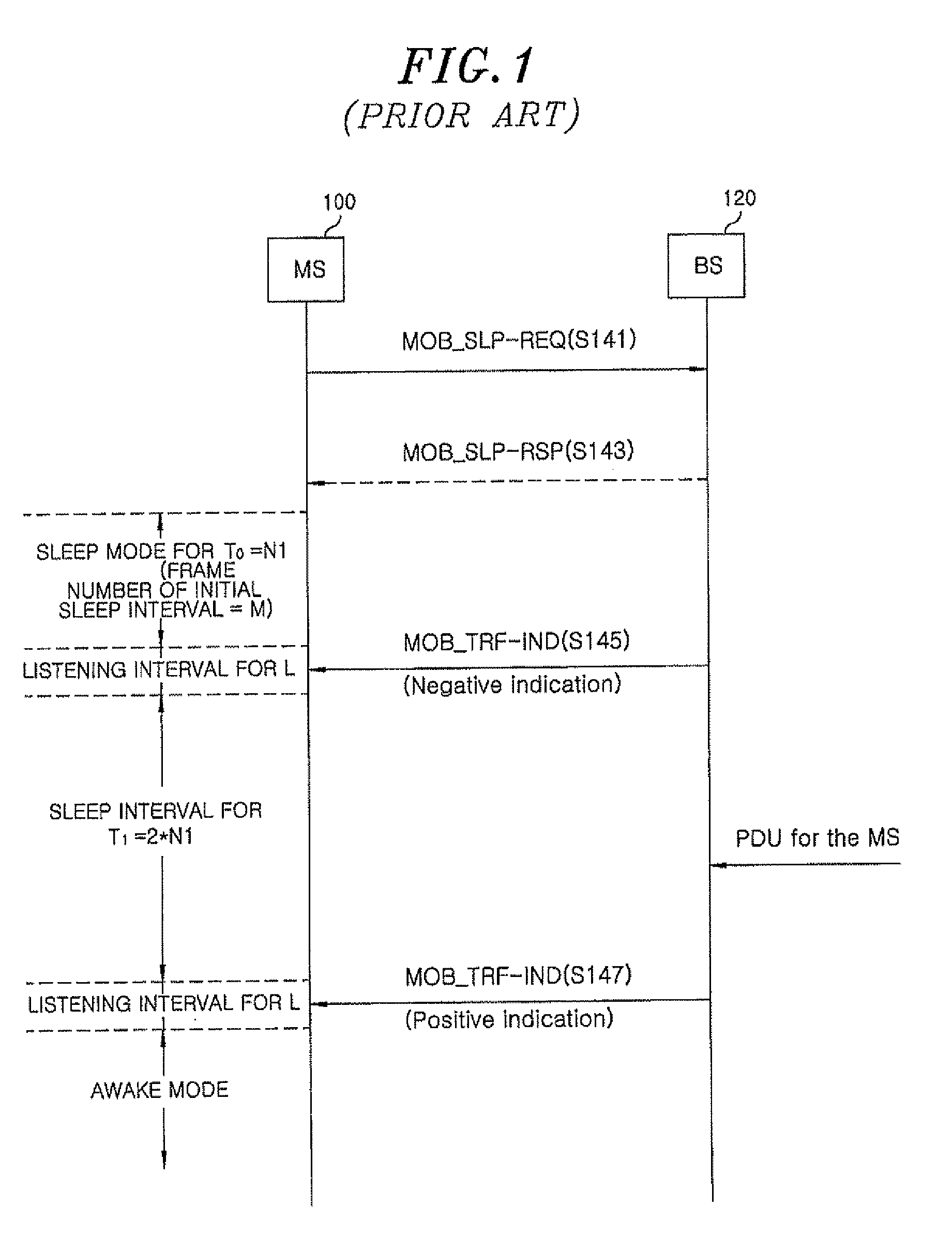
Further, implementation of sleep mode is optional for the MS according to the IEEE 802.16e standard, however, the MS not supporting sleep mode keeps monitoring the downlink all the time even when it does not receive data from the BS or transmit data to the BS, resulting in high power consumption.
However, if the conventional binary exponential algorithm is applied to these latest communication systems, power efficiency achieved by the sleep mode is reduced since transitions between access mode and sleep mode are unnecessarily frequent, it may degrade overall performance of the wireless communication systems.

Method used


Image

  • Method and apparatus for controlling sleep mode in wireless communication networks
  • Method and apparatus for controlling sleep mode in wireless communication networks
  • Method and apparatus for controlling sleep mode in wireless communication networks

Examples


first embodiment

[0029]FIG. 3 is a flow chart describing a method for controlling sleep mode in a wireless communication network in accordance with the present invention.

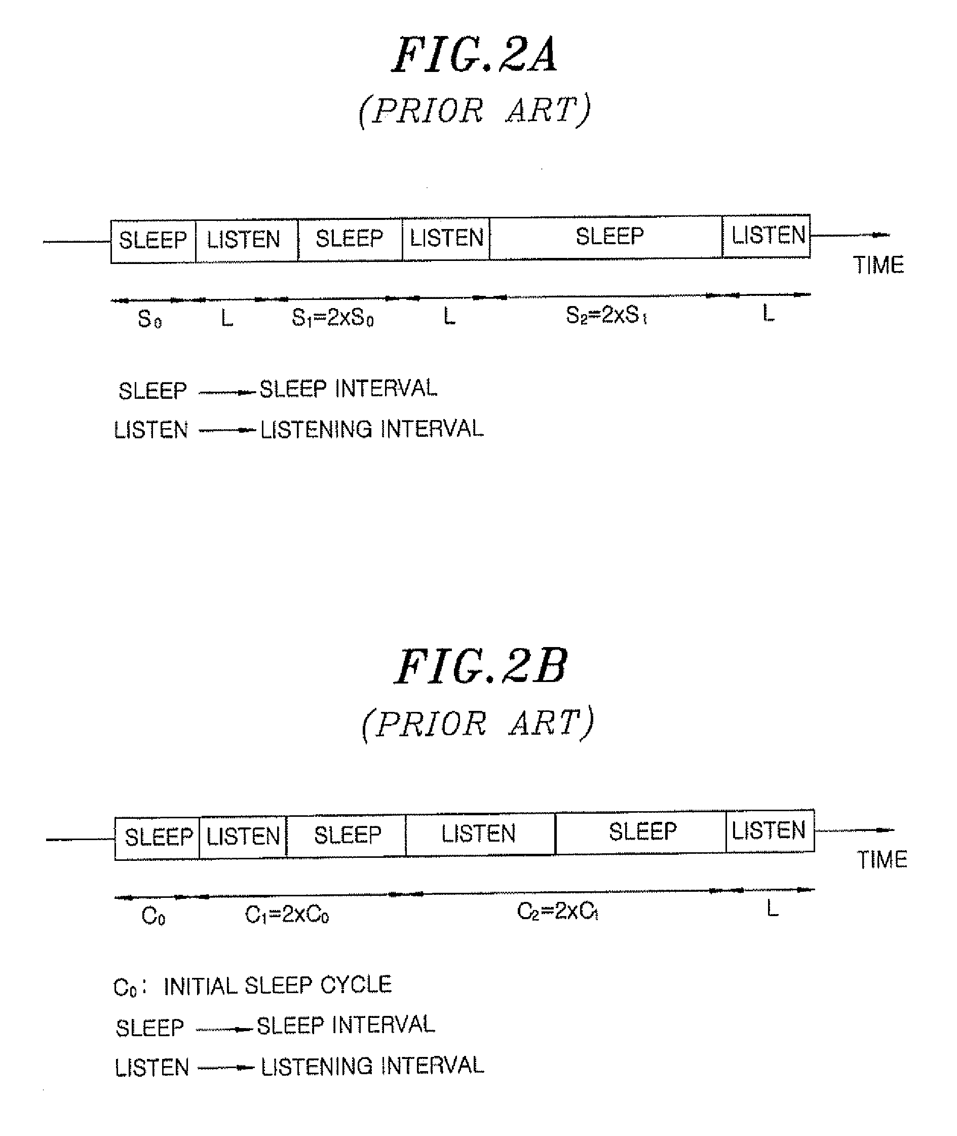
[0030]First, in step S201, a BS and an MS 700 determine various parameters necessary for the mode transition operation. For example, a length of initial sleep duration T0, the length of the maximum sleep duration Tmax, the number of additional consecutive sleep duration m upon arrival of packets, the maximum N-ary exponent Imax, the length of a time-out for retransmission R, the maximum number of allowed retransmissions Nmax, the required transmission delay constraint D* and the size of multiple packets M can be determined. Here, the length of the sleep duration corresponds to the length of each sleep interval S0, S1 or S2 in the wireless communication system based on the IEEE 802.16e standard shown in FIG. 2A, whereas it corresponds to the length of each sleep cycle C0, C1 or C2 in the wireless communication system based on the IEE...

second embodiment

[0052]FIG. 4 is a flow chart describing a method for controlling sleep mode in a wireless communication network in accordance with the present invention when a wireless communication system based on the IEEE 802.16e standard is employed.

[0053]First, in step S301, a BS and an MS determine various parameters required for the mode transition operation. For example, the length of an initial sleep interval S0, the length of the maximum sleep interval Smax, the number of additional consecutive sleep intervals m upon arrival of packets, the maximum N-ary exponent Imax, the length of a time-out for retransmissions R, the maximum number of allowed retransmissions Nmax, the required transmission delay constraint D and the threshold value M for the maximum number of packets allowed for one-time downlink transmission can be determined.

[0054]The above parameters can be determined by a sleep request (MOB_SLP-REQ) message and a sleep response (MOB_SLP-RSP) message exchanged between the BS and the ...

third embodiment

[0075]FIG. 5 is a flow chart describing a method for controlling sleep mode a wireless communication network in accordance with the present invention when a wireless communication system based on the IEEE 802.16m standard is employed.

[0076]First, in step S401, a BS and an MS determine various parameters required for the mode transition operation. For example, the length of an initial sleep cycle Co, the length of the maximum sleep cycle Cmax, the number of additional consecutive sleep cycles m upon arrival of packets, the maximum Nary exponent Imax, the length of a time-out for retransmission R, the maximum number of allowed retransmissions Nmax, the required transmission delay constraint D* and the threshold value M for the maximum number of packets allowed for one-time downlink transmission can be determined.

[0077]The above parameters can be determined by a sleep request (MOB_SLP-REQ) message and a sleep response (MOB_SLP-RSP) message exchanged between the BS and the MS. For examp...


PUM


Abstract

A method for controlling sleep mode of a base station and a mobile station in wireless communication networks, including: determining N of the N-ary exponential sleep mode to decide a length of sleep duration including a sleep interval; measuring downlink traffic addressed to the mobile station at the beginning of a listening interval right after the sleep interval; and when there exist downlink traffic, confirming whether the measured downlink traffic satisfies a mode transition condition. The method further includes: conducting a sleep interval of the next sleep duration of which the length is determined by multiplying the length of the current sleep duration by N unless the downlink traffic satisfies the mode transition condition; and transmitting the downlink traffic to the mobile station when m times the additional consecutive sleep duration is expired or when the measured amount of the downlink traffic satisfies the mode transition condition.

Description

FIELD OF THE INVENTION[0001]The present invention relates to a method and an apparatus for controlling sleep mode in wireless communication networks; and, more particularly, to a method and an apparatus for maximizing power saving by lengthening sleep duration through adoption of the N-ary exponential sleep mode of a base station and a mobile station in the wireless communication networks.BACKGROUND OF THE INVENTION[0002]In general, a communication system has been developed to provide high quality service capable of transmitting and receiving massive data at high speeds. In particular, demands for wireless communication network environments have recently increased. Due to a limited battery life of a mobile station (hereinafter, referred to as “MS”), power consumption of the MS is one of the factors significantly affecting overall performance of the wireless communication systems.[0003]Sleep mode of a base station (hereinafter, referred to as “ES”) and an MS can be employed to effici...

Claims


Application Information

Patent Timeline
Patent Type & Authority Applications(United States)
IPC IPC(8): H04W52/02H04W88/02
CPCH04W52/0216Y02B60/50H04W88/02Y02D30/70H04W52/02
Inventor SUNG, DAN KEUNPARK, YUNJU
Owner KOREA ADVANCED INST OF SCI & TECH
Learn More