High-precision signal detection for high-speed receiver

a signal detection and high-precision technology, applied in the field of high-speed receiver signal detection circuits, can solve problems such as the failure of the signal detection system to recognize a valid incoming data signal, and achieve the effect of maximizing power savings

Inactive Publication Date: 2010-01-05
MARVELL ASIA PTE LTD
View PDF15 Cites 22 Cited by
  • Summary
  • Abstract
  • Description
  • Claims
  • Application Information

AI Technical Summary

Benefits of technology

[0004]In accordance with this invention, a signal detector for detecting the presence of incoming data is provided. The signal detector according to the invention may be used as a trigger to activate, on the arrival of incoming data, a receiver that in the absence of data has been turned off, or placed in a low-power mode. Although the frequency of the incoming data may be high, such as in the gigabit Ethernet example above, it is desirable for the signal detector to operate at low power as part of the low-power mode of the receiver. Therefore, in accordance with the invention, the signal detector preferably operates at a lower clock speed than the incoming data to conserve power, and also preferably operates asynchronously of the incoming data to avoid the need to perform clock recovery operations on the incoming data. This allows the clock recovery portion of the receiver to remain in the low-power mode, along with most of the receiver, to maximize power savings. Essentially the only portions of the receiver that need to remain powered up preferably are the signal detector of the present invention, and a bias current generator.

Problems solved by technology

However, if the sampling frequency, as generated locally, turns out, by chance, to be an integer fraction of the data frequency, and if, also by chance, the first sample is at or near a zero crossing of the data signal, so that it does not exceed the threshold, then each subsequent sample also will be at or near a zero crossing, and the signal detector may fail to recognize a valid incoming data signal.

Method used


Image

  • High-precision signal detection for high-speed receiver
  • High-precision signal detection for high-speed receiver
  • High-precision signal detection for high-speed receiver

Examples


embodiment 30

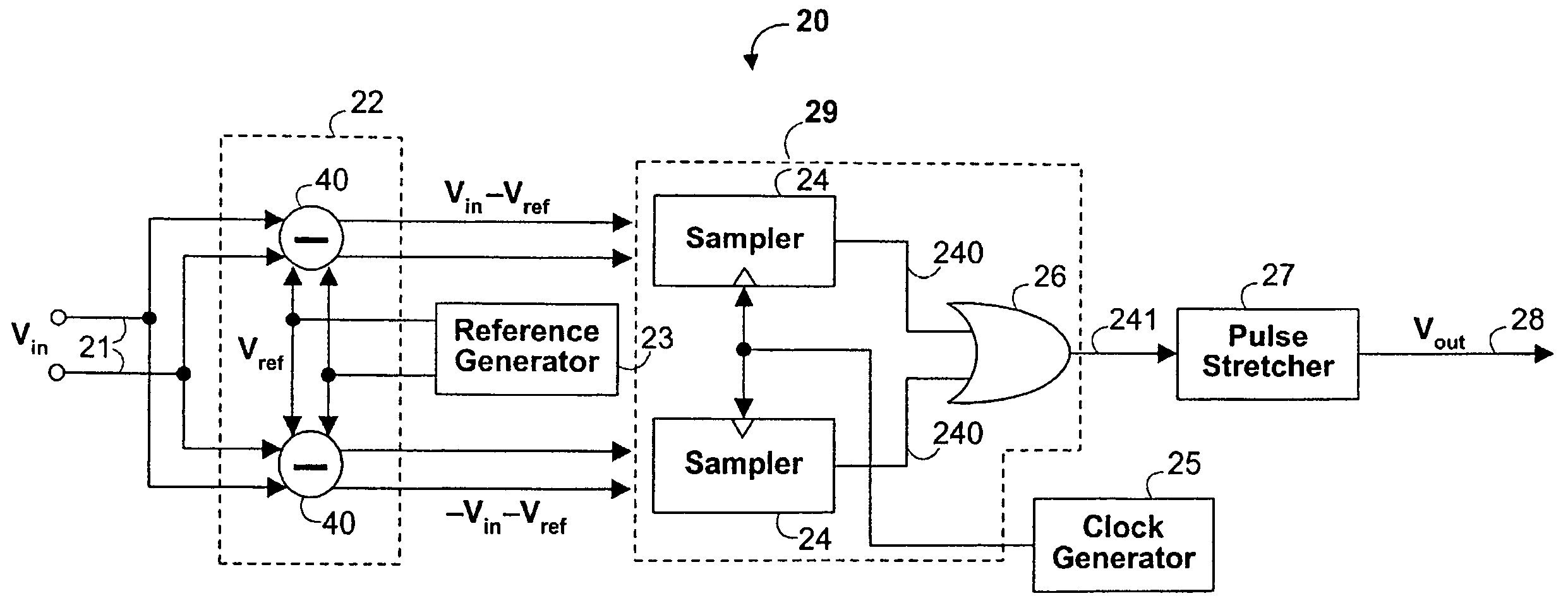
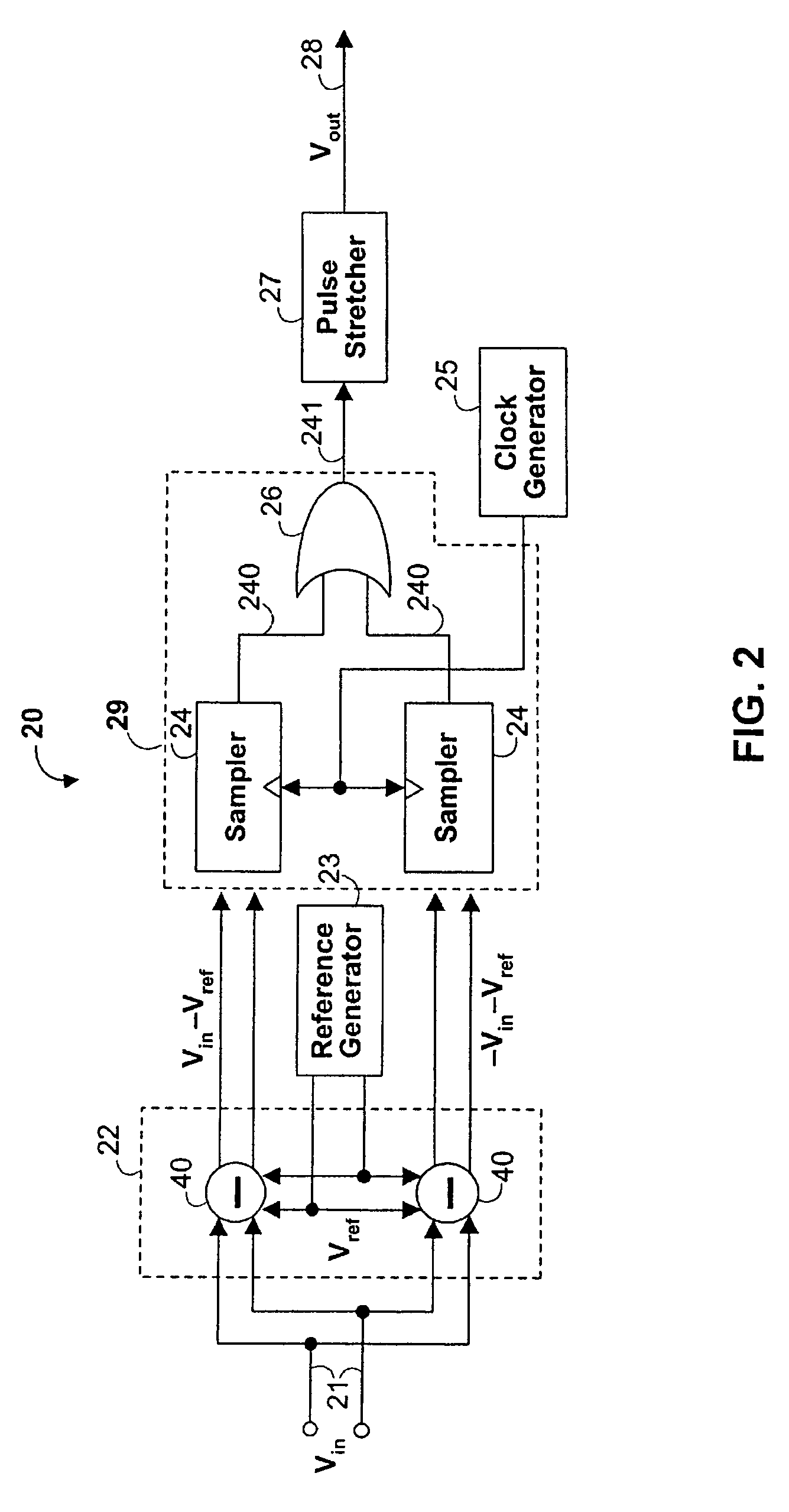
[0029]Signal 10, input at 21, is compared at comparison signal generator circuitry 22 to a reference voltage generated by reference voltage generator 23. It is preferable that in the case of a differential signal 10, the reference voltage have a common mode identical or nearly identical to the common mode of signal 10, so that an accurate difference is compared to the threshold level. A preferred embodiment 30 of a reference voltage generator capable of generating a reference signal with the appropriate common mode value is shown in FIG. 3.

[0030]Reference voltage generator 30 preferably includes a two-stage amplifier 31, a constant current source 32 and resistor ladder 33 connected between constant current source 32 and the output of two-stage amplifier 31. It is preferable that all resistors in resistor ladder 33 have the same resistance value, but it is only necessary the members of each pair of resistors about midpoint 330 have identical values. Thus, both resistors 331 preferabl...

embodiment 50

[0037]It is desirable that signal 241 be high long enough to activate the remainder of the receiver. A suitable duration might be twice the period of the clock used in the logic circuit involved—e.g., in the case of a receiver (not shown) having a physical coding sublayer (PCS) sampling clock of 40 ns, signal 241 preferably should be high for 80 ns. To achieve that result, pulse stretcher 27 preferably elongates the duration of signal 241. One preferred embodiment 50 of pulse stretcher 27 is shown in FIG. 5.

[0038]In pulse stretcher 50, signal 241 preferably is input to both a strong NMOS transistor 51 and a weak PMOS transistor 52, having a shared output 53 connected both to Schmitt trigger 54 and to ground through capacitor 55. If signal 241 goes high, strong NMOS transistor 51 will quickly discharge capacitor 55, causing Schmitt trigger 54 to hold a zero output 540 which is inverted by inverter 56 to produce a high on signal detect output 28, which will remain until capacitor 55 c...

embodiment 60

[0039]A preferred embodiment 60 of a sampling clock generator 25 is shown in FIG. 6. Sampling clock generator 25 preferably includes a main oscillator 61 and a low-speed oscillator 62. Preferably, both oscillators 61, 62 are three-stage ring oscillators. Each ring oscillator 61, 62 preferably includes a NAND-gate 600 in its respective ring which can be used to turn off clock generator 25 by applying a “0” at input 601 to force a “1” output from each NAND-gate 600 and thereby stop each oscillator 61, 62 from oscillating.

[0040]Each stage 63 of ring oscillator 61 includes an RC circuit 64 that governs the frequency of output 65. RC circuit 64 preferably includes a resistor or other resistance 40 and two capacitors 641, 642. Each capacitor 642 preferably is connected between resistor 640 and ground, while each capacitor 641 preferably is connected between resistor 640 and the output of oscillator 62. As the output voltage 70 (see FIG. 7) of oscillator 62 varies, the voltage across each ...


PUM


Abstract

In a high-precision signal detection apparatus and method for a high-speed receiver, signal detection occurs asynchronously of the incoming data. A comparison clock is generated by an oscillator whose effective capacitance is varied by a second, lower speed oscillator connected to the capacitance. This prevents the asynchronous sampling that occurs in a zero-crossing position in the incoming data from remaining in that position in subsequent sampling cycles, so that a valid signal is not missed by the detector.

Description

CROSS REFERENCE TO RELATED APPLICATION[0001]This claims the benefit of commonly-assigned U.S. Provisional Patent Application No. 60 / 599,724, filed Aug. 6, 2004, which is hereby incorporated herein by reference in its entirety.BACKGROUND OF THE INVENTION[0002]This invention relates to a signal detector circuit for a high-speed receiver. More particularly, this invention relates to a signal detector circuit that operates asynchronously of the received data and at a lower frequency, but nevertheless detects with high-precision the presence of incoming data.[0003]High-speed receivers, such as are used in 10 Mbps (i.e., 10BASE-T) and 100 Mbps (i.e., 100BASE-T) Ethernet applications compliant with the IEEE 802.3 standard, gigabit Ethernet (i.e., 1000BASE-T) applications (IEEE 802.3ab), and 10 Gigabit Ethernet (i.e., 10GBASE-T) applications (IEEE 802.3an), are frequently idle, insofar as there may not be incoming data to process. (All references herein, including in the claims that follow,...

Claims


Application Information

Patent Timeline
Patent Type & Authority Patents(United States)
IPC IPC(8): H04L27/06
CPCH04L27/0006Y02B60/50H04W52/0232Y02D30/70
Inventor SAVOJ, JAFARROO, PIERTE
Owner MARVELL ASIA PTE LTD
Why Eureka
Try Eureka