Pitch control system

Inactive Publication Date: 2011-06-30
VESTAS WIND SYST AS
View PDF14 Cites 31 Cited by
  • Summary
  • Abstract
  • Description
  • Claims
  • Application Information

AI Technical Summary

Benefits of technology

[0006]The present invention seeks to provide an improved way of eval

Problems solved by technology

Pitch system are subject to faults during use, such faults can relate to bearing faults or faults in other pitch system components.
Bearing damage can e.g. result from corrosion, friction in the pitch system mechanics, lack of grease, fatigue of damaged pi

Method used


Image

  • Pitch control system
  • Pitch control system
  • Pitch control system

Examples


Embodiment Construction

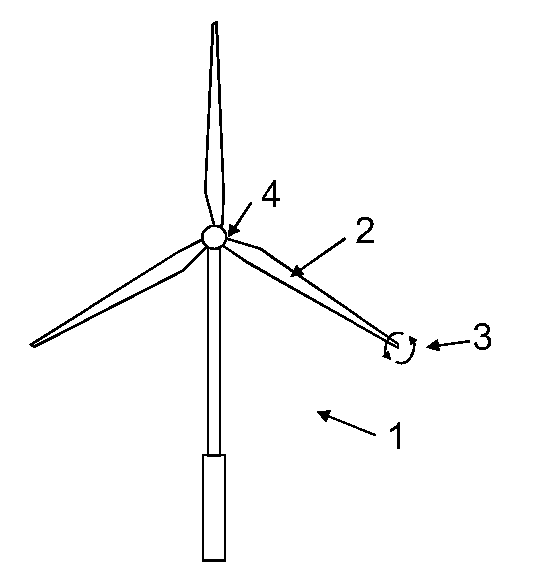
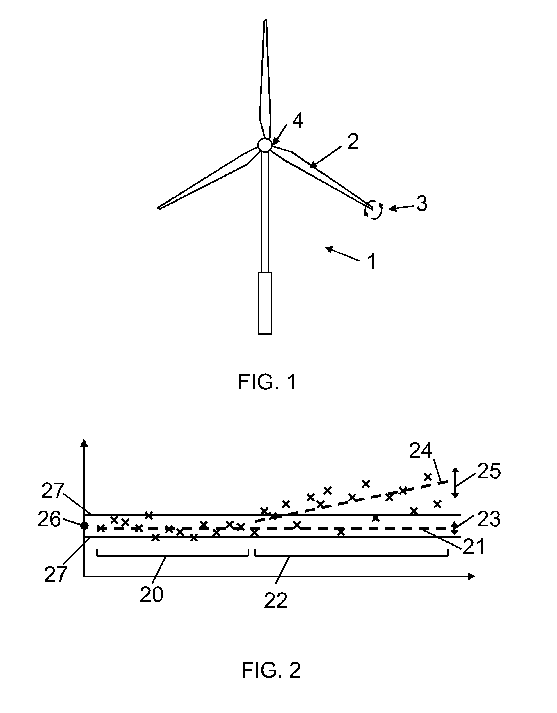
[0047]FIG. 1 schematically illustrates a wind turbine generator (WTG) 1 with three rotor blades 2. Moreover, the WTG 1 comprises a tower and a nacelle. The rotor blades comprise a blade pitch system for operating the blade pitch, here schematically illustrated by the curved arrows 3. Each rotor blade is attached to the nacelle, and in the joint between the rotor blades and the nacelle the blade pitch system 4 is placed for enabling pitching of the blades. The pitching of the blades is controlled by a pitch control system (not shown) by applying command signals, also referred to as pitch demands, and receiving response signals. In a first type of embodiment, the rotor blades are pitched by a common blade pitch system, so that all rotor blades are pitched together, whereas in a second type of embodiment, each of the rotor blades are pitched by independent blade pitch systems, so that each rotor blade may be pitched individually. In both types of systems, the pitch control system may m...


PUM


Abstract

The present invention relates to a pitch control system for operating the blade pitch of the rotor blades of a wind turbine generator. A method is disclosed wherein a command signal or pitch demand is applied to the blade pitch system of the rotor blades and the resulting response signal or pitch response is received. The received pitch response is compared to a reference and a signal indicative of a pitch system fault may be generated if a difference between the response signal and the reference is detected as being larger than a preset criterion. The deviating behaviour of a blade pitch system can thereby be detected which enables a testing or monitoring of the condition of the pitch system of the rotor blades of a wind turbine generator.

Description

FIELD OF THE INVENTION[0001]The present invention relates to a pitch control system for operating the blade pitch of the rotor blades of a wind turbine generator. In particular, the present invention relates to testing operational signals of a blade pitch system in order to detect pitch system faults.BACKGROUND OF THE INVENTION[0002]One of the fundamental operating components of wind turbine generators is the pitch system for adjusting the pitch of the rotor blades during operation. An important element in the pitch system is the pitch bearing.[0003]Pitch system are subject to faults during use, such faults can relate to bearing faults or faults in other pitch system components.[0004]Bearing damage can e.g. result from corrosion, friction in the pitch system mechanics, lack of grease, fatigue of damaged pitch bearings, etc. Damaged bearings increase the risk of blade pitch blocking which can be crucial for the loads on the turbine. Moreover, the delivery time of bearings is typicall...

Claims


Application Information

Patent Timeline
IPC IPC(8): F03D7/00
CPCF03D7/0224F03D7/024F03D11/0091F05B2240/50Y02E10/722F05B2270/107F05B2270/309F05B2270/328Y02E10/723F05B2260/83F03D17/00Y02E10/72
Inventor MIRANDA, ERIK CARL LEHNSKOVJEPPESEN, OLE MOLGAARDLAURITSEN, STEEN MORTEN
Owner VESTAS WIND SYST AS
Why Eureka
Try Eureka