Control System in Vehicle, Wheelie Determining Method, and Driving Power Suppressing Method

a control system and vehicle technology, applied in the direction of pedestrian/occupant safety arrangement, instruments, tractors, etc., can solve the problems of difficult to accurately detect whether or not the wheelie is occurring in the conventional control system using the acceleration sensor, noise output of the acceleration sensor, fluctuation in the gravitational force component of the detected acceleration, etc., to achieve the effect of suppressing the generated driving power and more driving power

Active Publication Date: 2011-06-30
KAWASAKI MOTORS LTD
View PDF1 Cites 22 Cited by
  • Summary
  • Abstract
  • Description
  • Claims
  • Application Information

AI Technical Summary

Benefits of technology

[0011]In accordance with this method, the rotational speed of the front wheel is detected, the change value of the rotational speed of the front wheel is calculated, and it is determined whether or not the wheelie has started based on the calculated change value. In this method, it is determined more accurately whether or not the wheelie has started based on a value which does not contain noise caused by the vibration of the vehicle body and the slope of the road surface.
[0012]According to another aspect of the present invention, a method of suppressing a driving power generated in a driving source when a wheelie is occurring in a vehicle including a front wheel which is a driven wheel and a rear wheel which is a drive wheel, the method comprising: a front wheel speed detecting step for detecting a rotational

Problems solved by technology

However, the output of the acceleration sensor contains noise.
During driving, the vehicle body vibrates due to an engine operation and bumps and depressions on a road surface, which results in a fluctuation in the gravitational force component of the detected acceleration.
For

Method used


Image

  • Control System in Vehicle, Wheelie Determining Method, and Driving Power Suppressing Method
  • Control System in Vehicle, Wheelie Determining Method, and Driving Power Suppressing Method
  • Control System in Vehicle, Wheelie Determining Method, and Driving Power Suppressing Method

Examples


embodiment 1

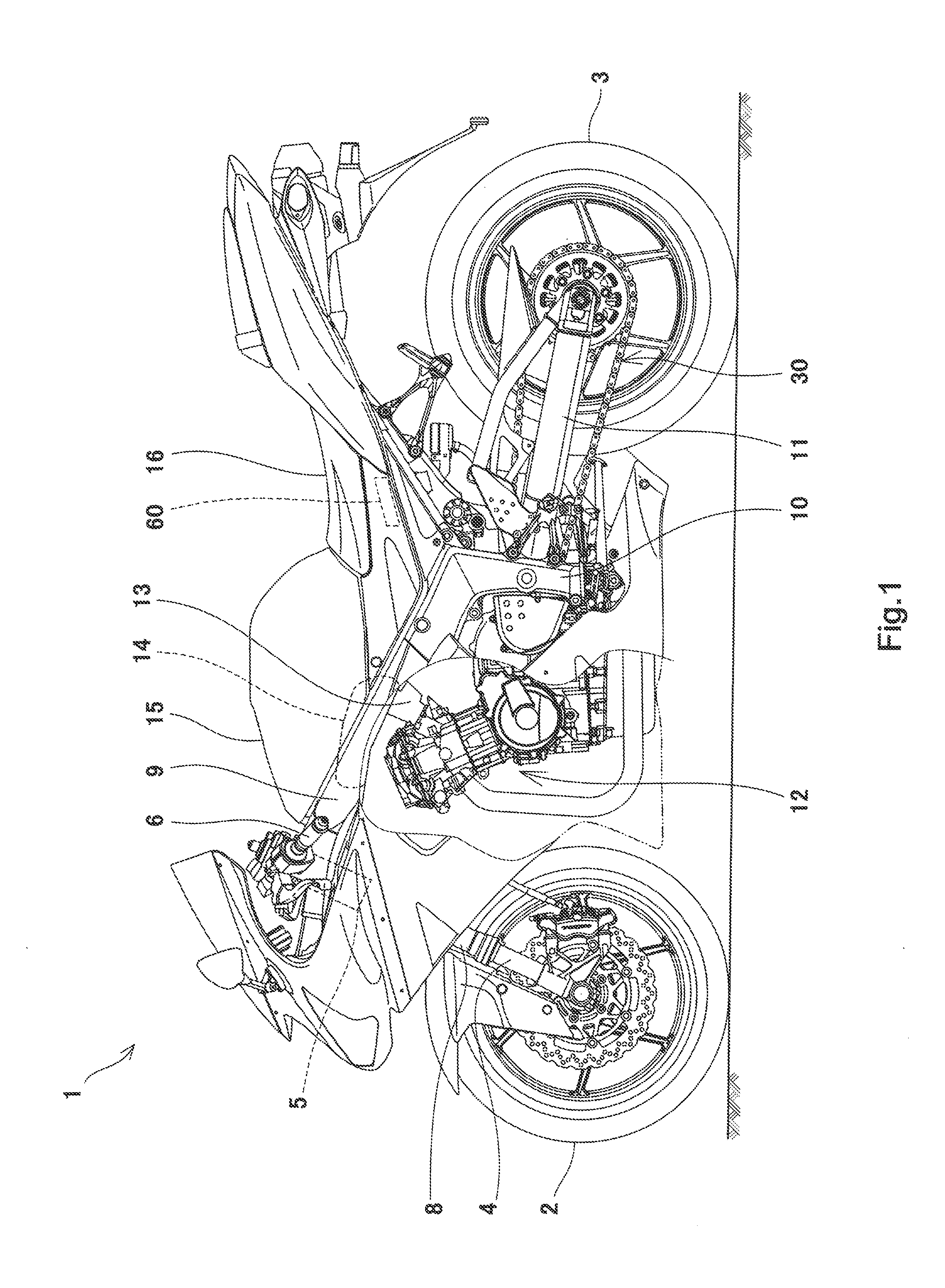
[0035]FIG. 1 is a left side view of a motorcycle 1 which is an exemplary vehicle including a control system according to Embodiment 1 of the present invention. Referring to FIG. 1, the motorcycle 1 includes a front wheel 2 which is a driven wheel at a front and a rear wheel 3 which is a drive wheel at a rear. The front wheel 2 is rotatably attached to a lower end portion of a front fork 4, which is extended substantially vertically. An upper end portion of the front fork 4 is coupled to a steering shaft (not shown) rotatably supported by a head pipe 5. An upper end portion of the steering shaft is coupled to a handle 6 having a pair of right and left grip members.

[0036]A front suspension 8 is provided at the front fork 4 such that the front suspension 8 is extendable and contractible. When a load is applied from a road surface to a vehicle body via the front wheel 2, the front suspension 8 is contracted to mitigate the load.

[0037]A pair of right and left main frame members 9 extend ...

embodiment 2

[0105]FIG. 14 is a flowchart showing a flow of a main control process executed by an electronic control unit in a control system according to Embodiment 2 of the present invention. The process flow in FIG. 14 is different from the process flow shown in FIG. 5 in that steps S10-S12 are inserted between step S9 and step S6 in the flow of FIG. 5, and a flag value is added (see S10, S13) in the flow of FIG. 5. A case where the process moves from step S1 to step S3 (S1: YES) is the same as that shown in FIG. 5 and is described above. In addition, the steps S2, S5, S7 and S8 are identical to those in Embodiment 1 as described above, except for where otherwise noted. Furthermore, the constituents shown in FIGS. 1 to 3 are used in Embodiment 2 and are designated by the same reference symbols.

[0106]Referring to FIG. 14, if it is determined that the flag value is not 0 (in other words 1 or 2) in step S1 (S1: NO), the wheelie determiner 64 executes the wheelie ending determination (S8). If it ...

embodiment 3

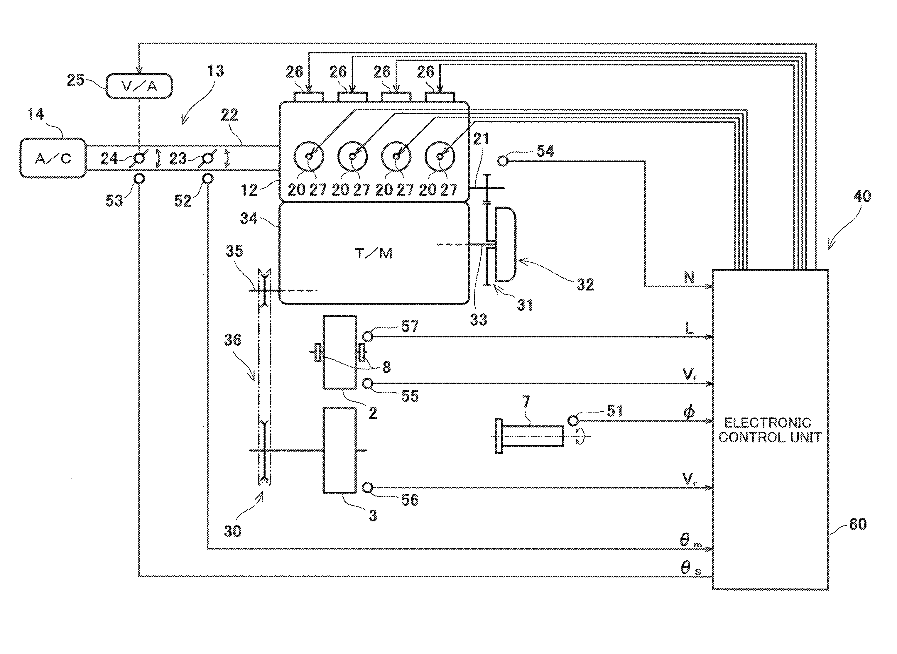
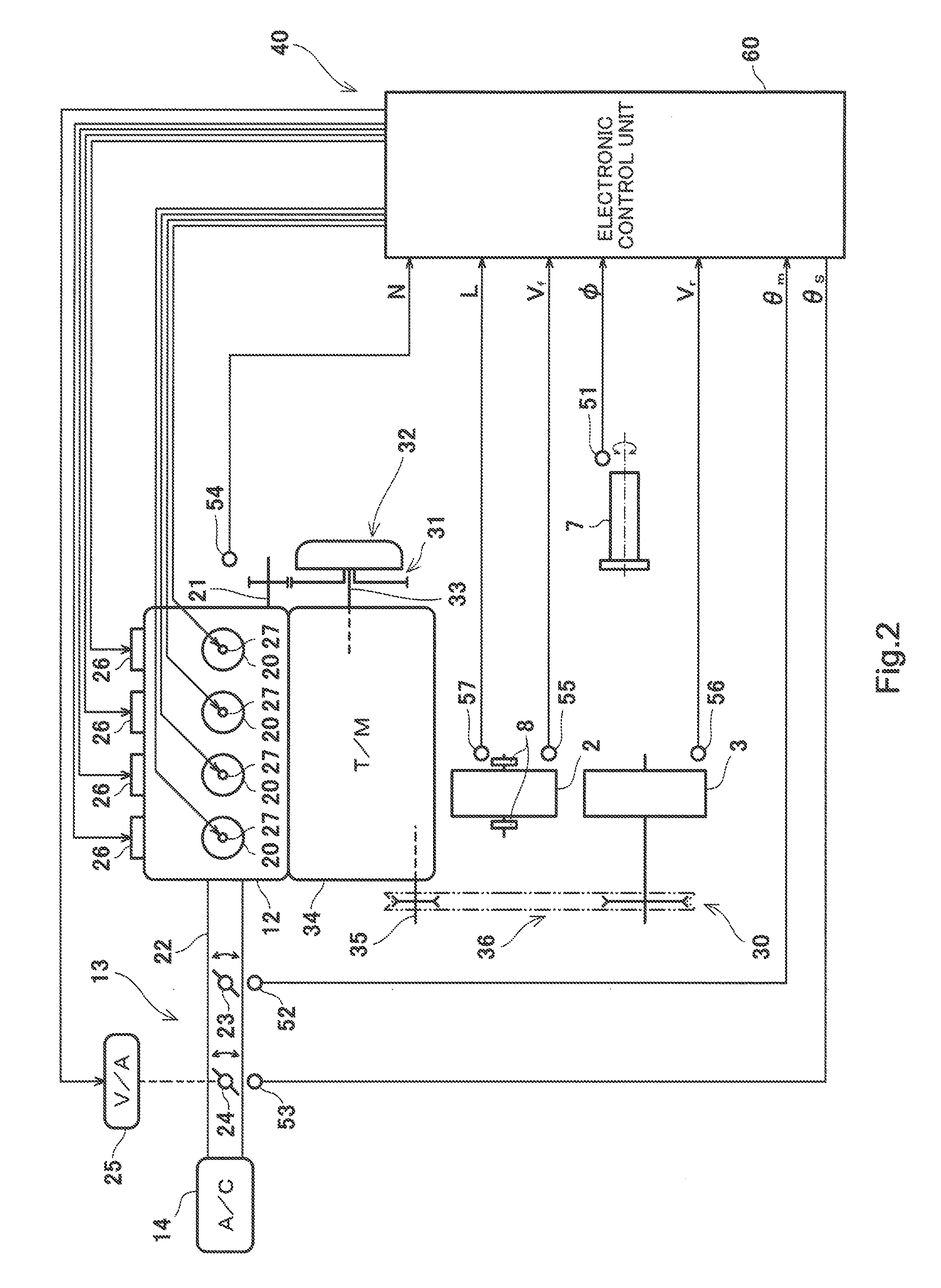
[0115]FIG. 17 is a block diagram showing a configuration of a control system 140 according to Embodiment 3 of the present invention. An electronic control unit 160 in the control system 140 in FIG. 17 is different from the electronic control unit 60 of Embodiment 1 in FIG. 3 in that a slip determiner 167 is incorporated into the electronic control unit 60. The other constituents are identical to those of Embodiment 1. They are designated by the same reference numerals and will not be described for the sake of brevity.

[0116]Referring to FIG. 17, the slip determiner 167 determines whether or not the speed difference equivalent value δ between the front and rear wheels 2 and 3, which is calculated by the speed difference equivalent value calculator 62, is not less than a slip threshold prestored in the memory 66 to determine whether or not the rear wheel 3 is slipping. The slip determiner 167 determines that the rear wheel 3 is slipping if the speed difference equivalent value δ betwee...


PUM


Abstract

A control system in a vehicle including a front wheel which is a driven wheel and a rear wheel which is a drive wheel, the control system including: a control unit configured to control a driving power generated in a driving source according to a driving state of the vehicle; and a front wheel speed sensor configured to detect a rotational speed of the front wheel; the control unit including: a wheelie determiner configured to determine whether or not a predetermined wheelie starting condition is met, based on a value detected by the front wheel speed sensor; and a driving power controller configured to suppress the driving power if the wheelie determiner determines that the predetermined wheelie starting condition is met.

Description

CROSS REFERENCE TO RELATED APPLICATION[0001]This application claims priority to and the benefit of Japanese Patent Application No. 2009-297940, filed on Dec. 28, 2009, the entire disclosure of which is incorporated herein by reference.BACKGROUND OF THE INVENTION[0002]1. Field of the Invention[0003]The present invention relates to a control system in a rear-wheel-drive vehicle, a method of determining whether or not a wheelie has occurred in the rear-wheel-drive vehicle and a method of suppressing driving power generated in a driving source in the vehicle.[0004]2. Description of the Related Art[0005]In rear-wheel-drive vehicles such as motorcycles, a wheelie sometimes occurs when a high engine driving power is transmitted to a rear wheel. Japanese Laid-Open Patent Application Publication No. 2002-70709 discloses a control system in a motorcycle for controlling an engine to reduce an engine driving power upon the wheelie starting.[0006]A conventional control system includes an acceler...

Claims


Application Information

Patent Timeline
IPC IPC(8): G06F19/00
CPCB60T8/175B60T8/1706
Inventor MATSUDA, YOSHIMOTO
Owner KAWASAKI MOTORS LTD
Why Eureka
Try Eureka