Measuring system having a measuring transducer of vibration-type

Active Publication Date: 2011-06-30
ENDRESS HAUSER FLOWTEC AG
View PDF15 Cites 42 Cited by
  • Summary
  • Abstract
  • Description
  • Claims
  • Application Information

AI Technical Summary

Benefits of technology

[0033]The invention as well as other advantageous embodiments thereof will now be explained in greater detail on the basis of examples of embodiments presented in the figures of the drawing. Equal parts are provided in all figures with equal reference characters; when perspicuity requires or it otherwise appears sensible, already ment

Problems solved by technology

A disadvantage of the solutions known from the state of the art for pressure measurement, especially also for pressure difference measuring by means of measuring transducer of vibration-type, is, however, to be seen in the fact that either correspondingly modified exciter mechanisms and/or correspondingly modified driver electronics need to be used, or, however, additional pressure sensors provided.
Associated therewith, both the design complexity of the measuring system as well as also the exper

Method used


Image

  • Measuring system having a measuring transducer of vibration-type
  • Measuring system having a measuring transducer of vibration-type
  • Measuring system having a measuring transducer of vibration-type

Examples


Embodiment Construction

[0042]While the invention is susceptible to various modifications and alternative forms, exemplary embodiments thereof have been shown by way of example in the drawings and will herein be described in detail. It should be understood, however, that there is no intent to limit the invention to the particular forms disclosed, but on the contrary, the intention is to cover all modifications, equivalents, and alternatives falling within the spirit and scope of the invention as defined by the intended claims.

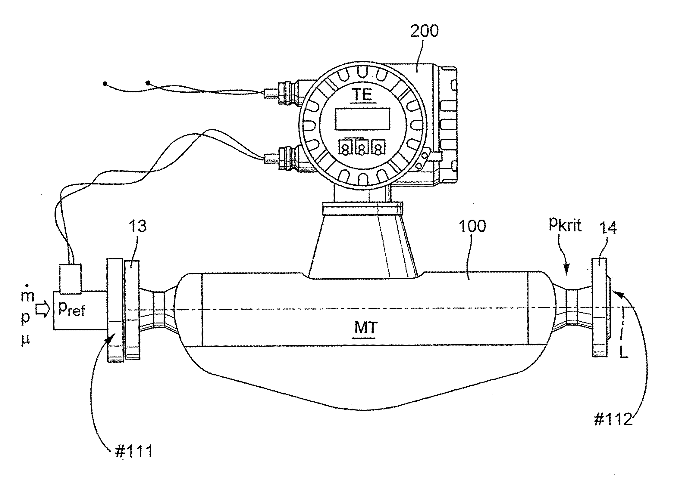
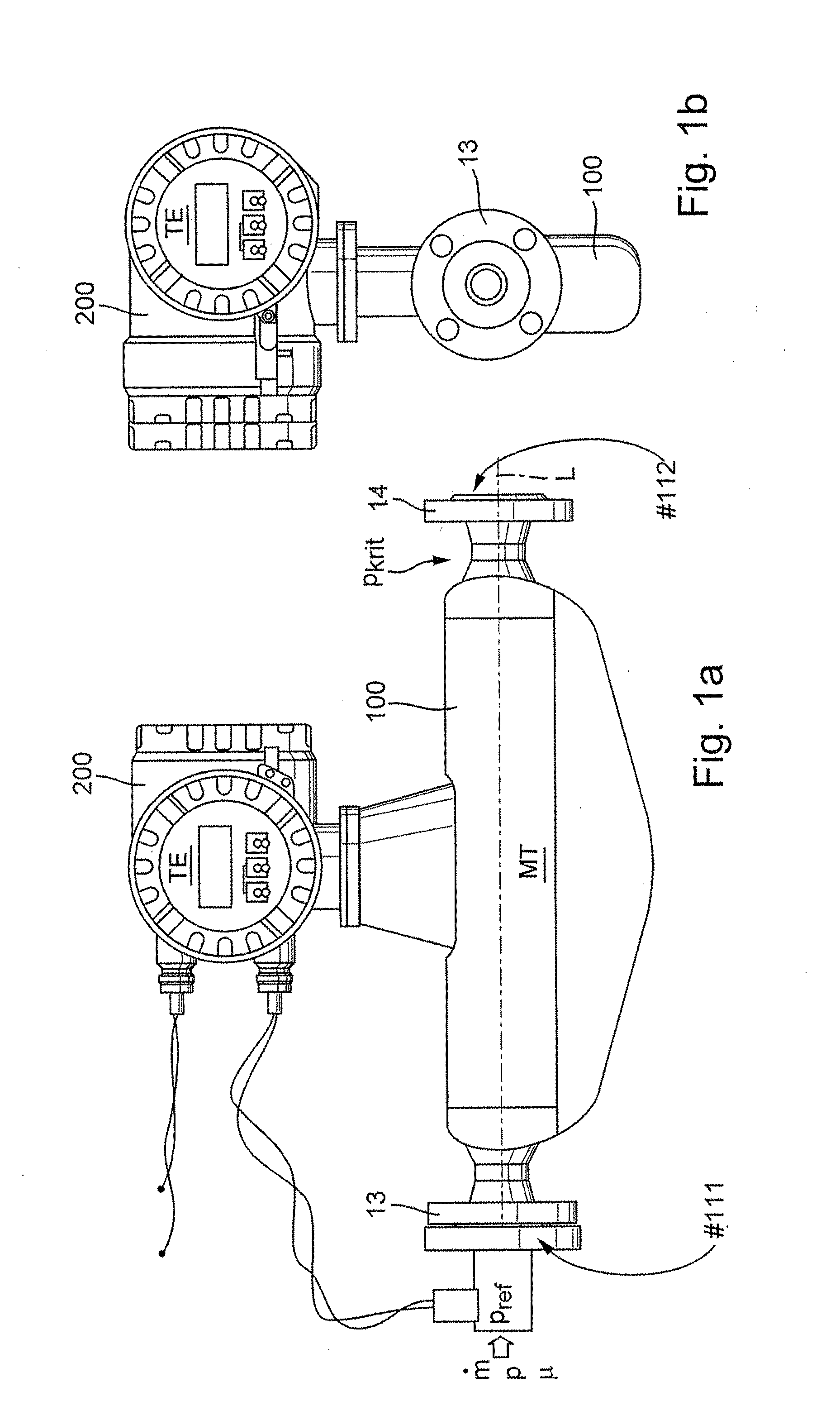
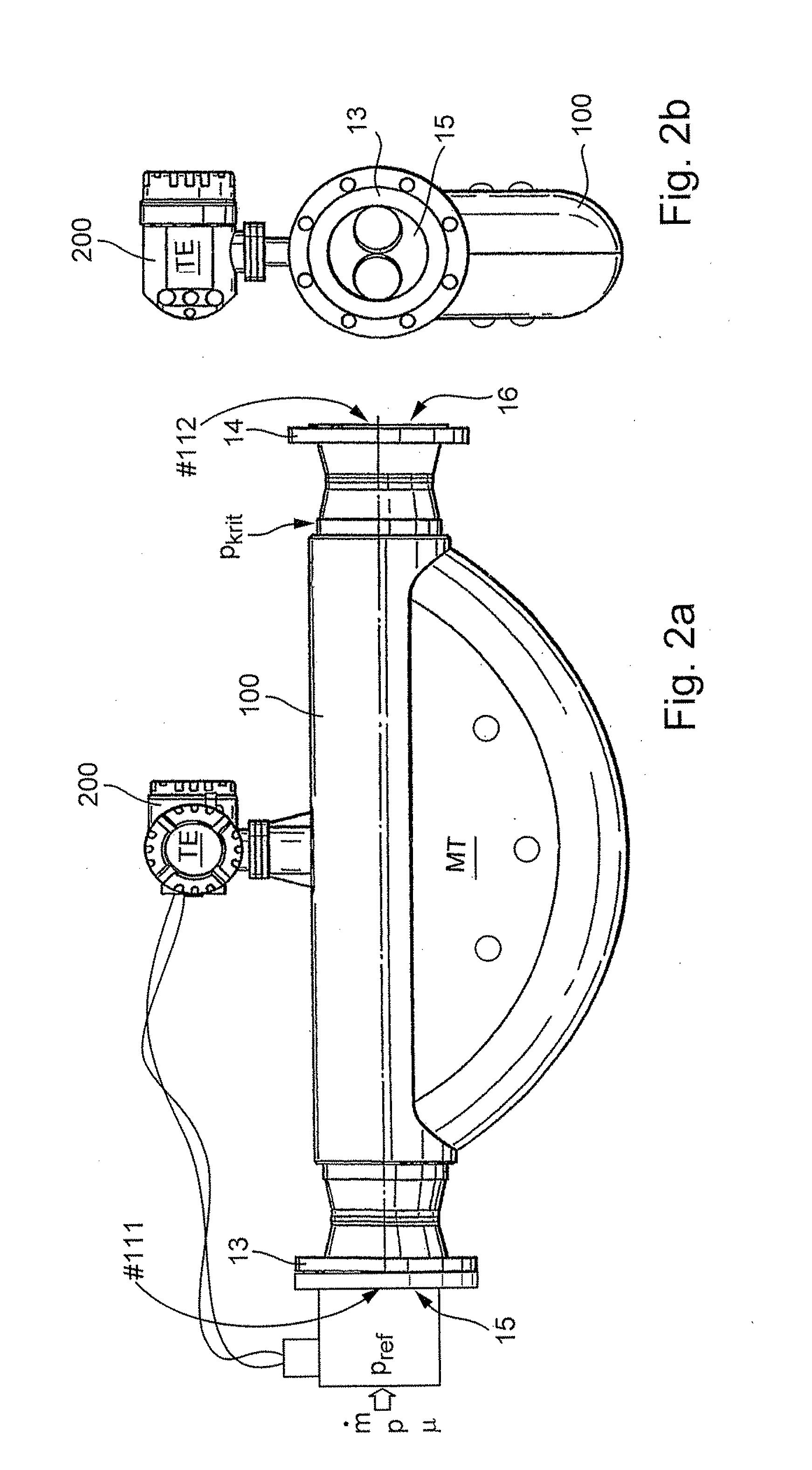
[0043]FIG. 1a, 1b, or 2a, 2b show, in each case, a variant of a measuring system suitable for flowable, especially fluid, media and insertable in a process line, for instance, a pipeline of an industrial plant, for example, a measuring system formed by means of a Coriolis, mass flow measuring device, a density measuring device, a viscosity measuring device or the like, which serves, especially, for measuring and / or monitoring a pressure difference of a medium flowing in the process li...


PUM


Abstract

The measuring system comprises: A measuring transducer of vibration-type, through which medium flows during operation and which produces primary signals corresponding to parameters, especially a mass flow rate, a density and/or a viscosity, of the flowing medium; as well as a transmitter electronics electrically coupled with the measuring transducer for activating the measuring transducer and for evaluating primary signals delivered by the measuring transducer. The measuring transducer includes at least one measuring tube for conveying flowing medium; at least one electro-mechanical, oscillation exciter for exciting and/or maintaining vibrations of the at least one measuring tube, a first oscillation sensor for registering inlet-side vibrations at least of the at least one measuring tube and for producing a first primary signal of the measuring transducer representing vibrations at least of the at least one measuring tube, and a second oscillation sensor for registering outlet-side vibrations at least of the at least one measuring tube and for producing a second primary signal of the measuring transducer representing vibrations at least of the at least one measuring tube. The transmitter electronics, in turn, delivers at least one driver signal for the oscillation exciter for effecting vibrations of the at least one measuring tube and generates, by means of the first primary signal and by means of the second primary signal, as well as with application of a Reynolds number, measured value representing a Reynolds number, Re, for medium flowing in the measuring transducer, a pressure difference, measured value, which represents a pressure difference occurring between two predetermined reference points in the flowing medium.

Description

CROSS-REFERENCE TO RELATED APPLICATION[0001]This application is a Nonprovisional which claims the benefit of U.S. Provisional Application No. 61 / 291,648 filed on Dec. 31, 2009.FIELD OF THE INVENTION[0002]The invention relates to a measuring system for flowable, especially fluid, media, especially a measuring system embodied as a compact, measuring device and / or as a Coriolis mass flow measuring device, wherein the measuring system comprises: A measuring transducer of vibration-type, through which medium flows during operation at least at times and and which generates primary signals influenced by at least one measured variable, especially a mass flow, a density, a viscosity, etc., characterizing the flowing medium; as well as a transmitter electronics electrically coupled with the measuring transducer and processing into measured values primary signals delivered by the measuring transducer.BACKGROUND OF THE INVENTION[0003]In industrial measurements technology, especially also in con...

Claims


Application Information

Patent Timeline
IPC IPC(8): G06F19/00
CPCG01F1/8436G01N11/02G01F1/8427G01F1/8477G01F1/8431G01F1/8413G01F1/8418
Inventor KUMAR, VIVEKANKLIN, MARTIN
Owner ENDRESS HAUSER FLOWTEC AG
Why Eureka
Try Eureka