Eureka AIR delivers breakthrough ideas for toughest innovation challenges, trusted by R&D personnel around the world.

Finite state machine architecture for software development

a software development and machine architecture technology, applied in the field of software application development methods and systems, can solve the problems of high life cycle costs, and high support activities, and achieve the effect of reducing life cycle costs and reducing inefficiencies associated with the knowledge gap between programmers and end-users

Active Publication Date: 2011-06-30
THE UNITED STATES OF AMERICA AS REPRESENTED BY THE SECRETARY OF THE NAVY
View PDF27 Cites 21 Cited by
  • Summary
  • Abstract
  • Description
  • Claims
  • Application Information

AI Technical Summary

Benefits of technology

[0006]The present disclosure provides a software architecture that reduces the need for involvement of high-level programmers in the life cycle of certain software applications by enabling development and maintenance of such applications without the use of high-level programming languages. As a result, the methods and systems of the present invention should reduce life cycle costs. Additionally, as the development and maintenance of the applications may be performed by properly trained technicians familiar with the requirements of the applications and the operational environments, but not necessarily familiar with abstract programming, the inefficiencies associated with the knowledge gap between the programmers and the end-users may be reduced. For example, the architecture of the present disclosure permits on-site trained, non-programmer technicians to work with end-users to provide application updates, rather than requiring communication with remote programmers who are less familiar with the actual deployment of the application.
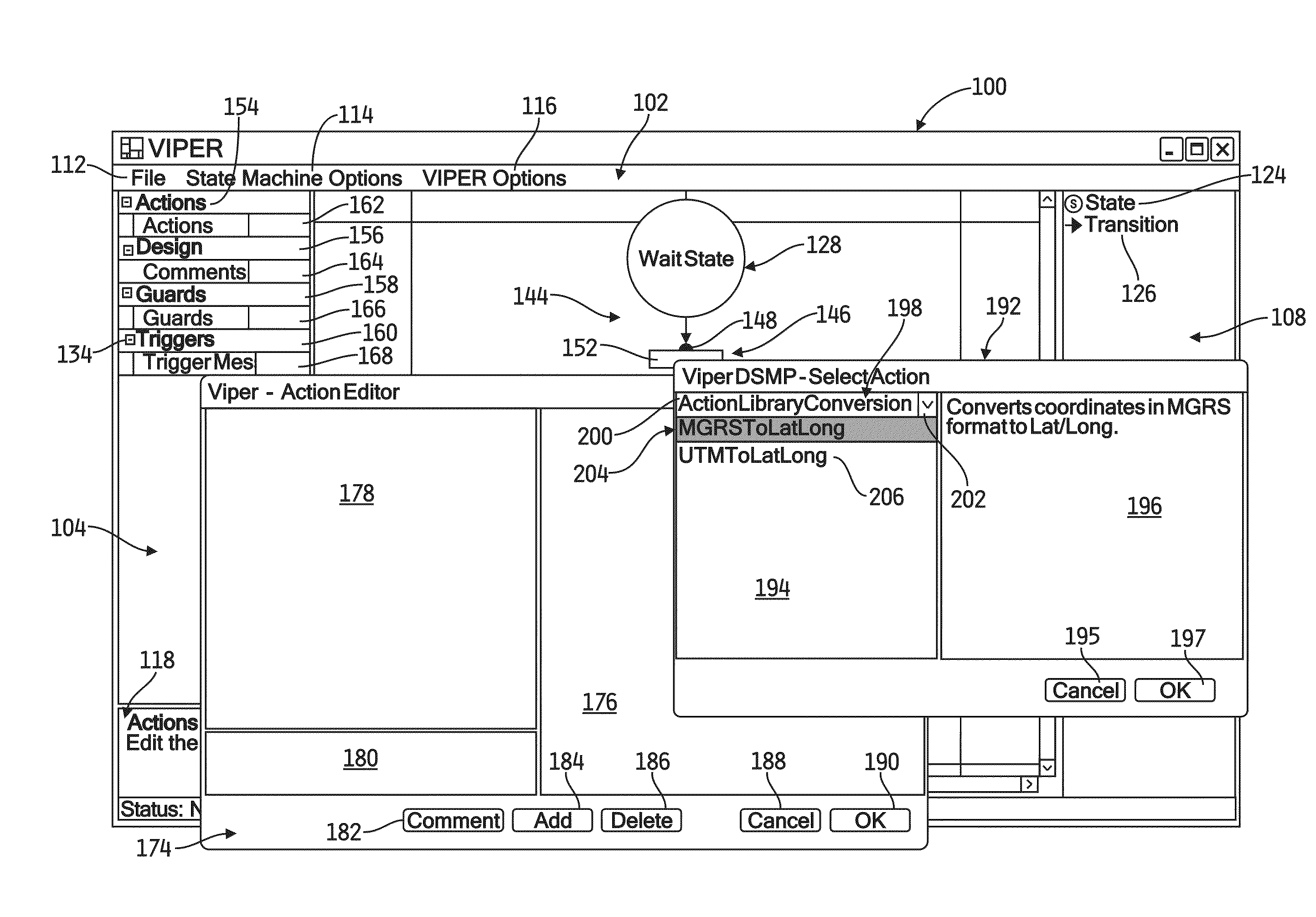
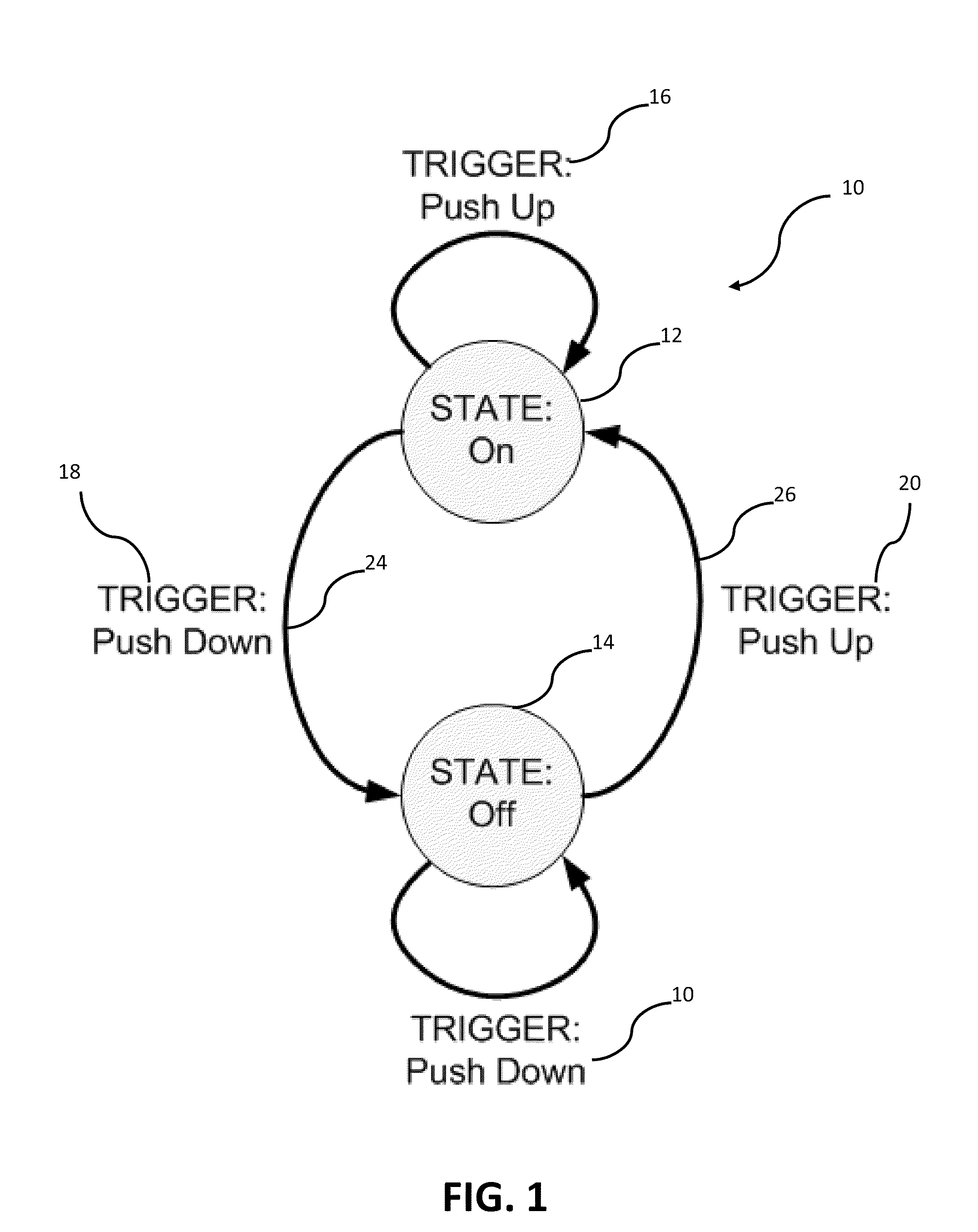
[0007]More specifically, the present disclosure provides a software architecture for development of applications having functionality that can be effectively modeled using finite state machine elements. This characteristic is common to many special purpose software applications that enable an end-user to perform a particular task or set of tasks that involve a manageable number of different stages or states. Although the present disclosure refers to the creation and maintenance of applications of relatively low complexity, it should be understood that, in theory, any software application can be modeled using finite state machine elements. The present system generally includes a dynamic state machine processor (DSMP) that manages execution of finite state machine elements representing the functionality of the software application (referred to hereinafter as an “FSM model”), an extensible graphic user interface (GUIX) with functionality that is entirely dependent upon the FSM model, and a visual interface for programming extensible routines (VIPER) that enables technicians without high-level programming experience (but trained on the use of VIPER) to create and modify FSM models using a graphic environment with drag / drop finite state machine elements.

Problems solved by technology

It is known that a substantial majority of the life cycle costs associated with many software applications are incurred in post-release support activities such as debugging, enhancing functionality, and adapting the applications to changes in the end-use environment.
These support activities are expensive because they require the involvement of highly skilled (and relatively highly compensated) programmers who must perform the often time consuming task of writing / rewriting and testing code in a high-level programming language.
Such high life cycle costs are particularly problematic for organizations that require large numbers of software applications because they perform a wide variety of tasks and / or multiple tasks that must be performed under changing operational environments.
The iterative development approach described above is especially inefficient for software applications that provide relatively simple functionality, a characteristic of many special purpose applications, because it employs highly skilled programmers using high-level programming languages to modify basic functions.
As indicated above, another problem with the conventional software development approach is the inefficiencies that arise from the knowledge gap between the programmers and the end-users about the needs to be addressed by a particular application.
The end-user is the expert on the requirements of the application, but can only provide feedback to the programmers because the end-user is typically not qualified to revise the application to incorporate the desired functionality.
This transfer of knowledge takes time, and invariably some portion of the end-user's feedback is lost in the process.
The situation is frequently made worse by the physical separation between the end-users and the programmers.

Method used


Image

  • Finite state machine architecture for software development
  • Finite state machine architecture for software development
  • Finite state machine architecture for software development

Examples


Embodiment Construction

[0019]For the purposes of promoting an understanding of the principles of the disclosure, reference will now be made to the embodiments illustrated in the drawings, which are described below. It will nevertheless be understood that no limitation of the scope of the disclosure is thereby intended. The disclosure includes any alterations and further modifications in the illustrated system and described method and further applications of the principles of the disclosure, which would normally occur to one skilled in the art to which the disclosure relates. Moreover, the embodiments were selected for description to enable one of ordinary skill in the art to practice and implement the principles described herein.

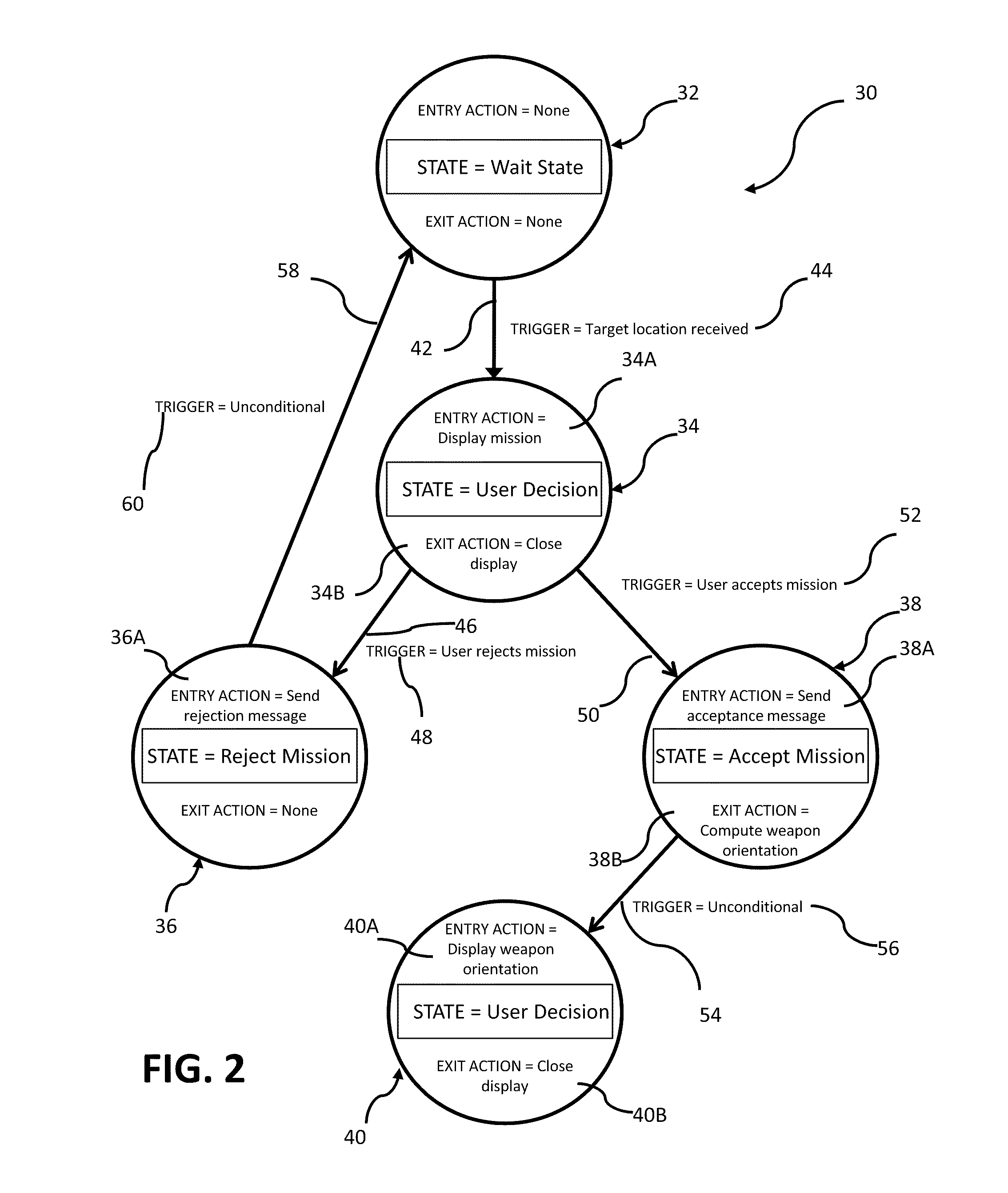
[0020]The following description uses the example of a fire control application for an end-user in a military operational environment. A fire control application is an example of a category of applications that may be characterized as mission control applications. Fire control appl...


PUM


Abstract

A system for developing an application program having functionality that corresponds to a finite state machine (FSM) model includes a visual interface that generates a graphical environment on a display for displaying an FSM model representing functionality of the program, a dynamic state machine processor that uses XML descriptions associated with the FSM model to generate the program executed at run-time, and an extensible graphic user interface that provides the end-user interface features to the end-user as generated during run-time by the processor based on the FSM model.

Description

STATEMENT REGARDING FEDERALLY SPONSORED RESEARCH OR DEVELOPMENT[0001]The invention described herein includes contributions by one or more employees of the Department of the Navy made in performance of official duties and may be manufactured, used and licensed by or for the United States Government for any governmental purpose without payment of any royalties thereon.FIELD OF THE DISCLOSURE[0002]The present disclosure relates generally to methods and systems for development of software applications, and more particularly to methods and systems for employing a finite state machine architecture to generate, modify, and maintain software applications.BACKGROUND AND SUMMARY OF THE DISCLOSURE[0003]The development of typical software applications of even nominal complexity requires the skills of programmers familiar with a middle-level or high-level programming language such as C++. Often, such programmers develop applications based on functional requirements specified by end-users of the ...

Claims


Application Information

Patent Timeline
Patent Type & Authority Applications(United States)
IPC IPC(8): G06F9/44G06F3/048
CPCG06F9/444G06F8/35G06F9/4498
Inventor CRUISE, ROBERT BHOCKENHEIMER, MATTHEW C.MISHLER, THOMAS H.SCHMIDT, PAUL L.BUSCH, THOMAS H.KITTINGER, LOGAN A.TURPIN, KEITH E.TOKARSKY, MATTHEW A.
Owner THE UNITED STATES OF AMERICA AS REPRESENTED BY THE SECRETARY OF THE NAVY
Why Eureka
Eureka Blog
Learn More