Regeneratively cooled synthesis gas generator

a synthesis gas generator and regenerative cooling technology, which is applied in the mechanical details of gasifiers, furnaces, lighting and heating apparatuses, etc., can solve the problems of low efficiency and achieve the effects of low cost, high reliability and low cos

Inactive Publication Date: 2005-07-26
GAS TECH INST +1
View PDF4 Cites 27 Cited by
  • Summary
  • Abstract
  • Description
  • Claims
  • Application Information

AI Technical Summary

Benefits of technology

[0008]Thus, the present invention provides a low cost, high reliability, and rapid start-up regeneratively cooled synthesis gas reactor, a coolant liner, and a method of producing syntheses gas in a regeneratively cooled reactor. Moreover, coolant liners in accordance with the principles of the present invention recover waste heat and produce steam at temperatures ranging from 700 to 800 degrees Fahrenheit by exchanging heat from the alkali and sulfur laden product gas streams. By low cost, herein, it is meant low life cycle costs relative to prior art non-regeneratively cooled synthesis gas reactors. By highly reliable, it is meant that the mean time between failures is greater than three years. By rapid start-up (and shut down), it is meant that gasifier start-up (and shut down) times are on the order of a few seconds.
[0009]Moreover, the current invention solves many of the problems associated with the prior art reactors by adapting the ceramic matrix composite structures taught in Boeing co-owned U.S. Pat. No. 6,418,973 which issued to Cox et al. Accordingly, the '973 patent is incorporated by reference as if set forth in full herein. By using these ceramic matrix composite materials, the present invention provides coolant liners and heat exchange surfaces with thin walls. Accordingly, the hot-side surfaces of the coolant liners will not exceed 2000 degrees Fahrenheit even when employed in a synthesis gas reactor. Additionally, by avoiding the use of metal substrates in the reactor's coolant liner, all alkali and sulfur corrosion associated with the formation of low temperature metal eutectics are eliminated from the coolant liner. Furthermore, high shear stresses at the metal to ceramic interfaces (because of thermal expansion coefficient mismatches) and the associated spalling are likewise eliminated.

Problems solved by technology

The low efficiency is partly due to the water slurry coal feed system used to continuously charge the gasifier with coal.

Method used


Image

  • Regeneratively cooled synthesis gas generator
  • Regeneratively cooled synthesis gas generator
  • Regeneratively cooled synthesis gas generator

Examples


Embodiment Construction

[0021]The following description of the preferred embodiment(s) is merely exemplary in nature and is in no way intended to limit the invention, its application, or uses.

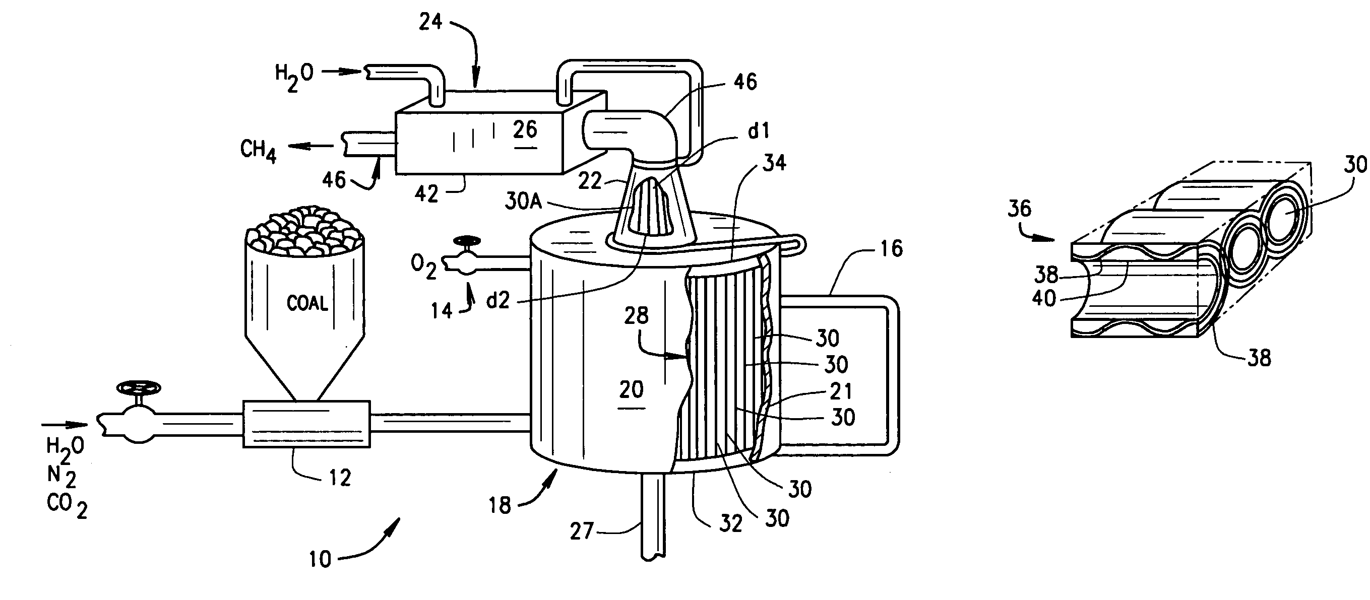
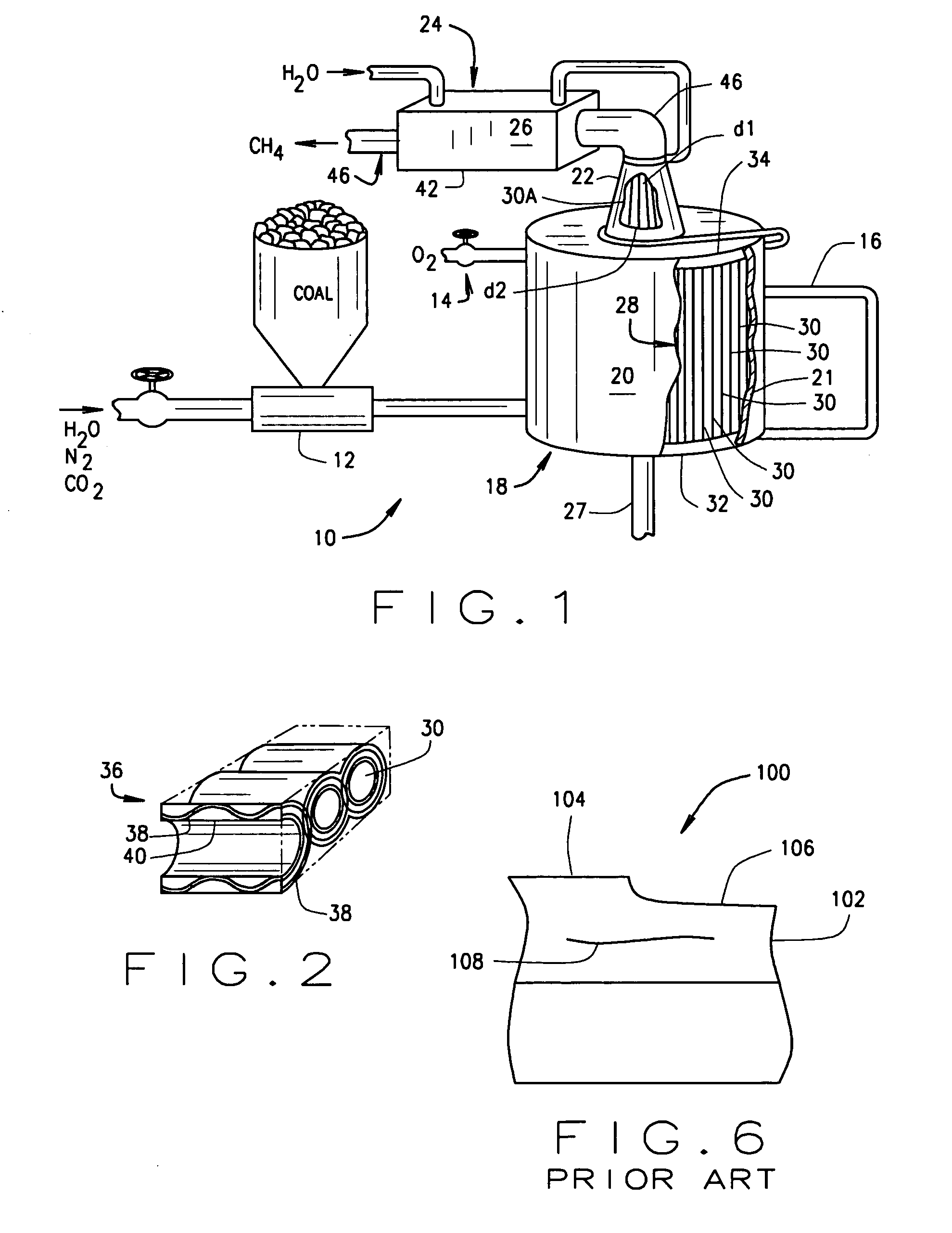
[0022]As shown in FIG. 1, a synthesis gas system 10 in accordance within the principles of the present invention includes a source of coal 12, a source of air (or oxygen) 14, a source of water (superheated or saturated steam typically at about 700 degrees Fahrenheit) 16, a reactor 18 including a wall (or pressure vessel shell) 20, an exit nozzle 22, and a waste heat recovery section 24. While the reactor 18 shown is a coal gasifier, the gasifier will be referred to as a reactor to illustrate that the present invention is not limited to coal gasifiers. Pulverized coal may be carried into the reactor by a water, a nitrogen, or a carbon dioxide based slurry.

[0023]Within the reactor, the oxygen and a portion of the coal react to provide the heat necessary for the synthesis gas reaction in which the remainder of the coal i...


PUM

PropertyMeasurementUnit
thicknessaaaaaaaaaa
temperatureaaaaaaaaaa
surface temperaturesaaaaaaaaaa

Abstract

A coolant liner for a carbonaceous fuel (coal or petcoke) gasification vessel including a ceramic composite panel and a method of cooling a vessel. The panel includes at least two layers of woven yarns of fibrous material and walls extending between the layers. Accordingly, the layers and the walls define coolant channels that extend in a warp direction. Moreover, one of the layers may be less than about 0.08 inches thick. Materials used to create the composite panel may include alumina, chromia, silicon carbide, and carbon. Additionally, the liners may be shaped in an arc or have coolant channels which vary in diameter in the warp direction. Additionally, the liner may abut a structural closeout of the vessel. The coolant liner provides a significantly more durable component than previously employed liners and is especially well suited to demanding service environments.

Description

FIELD OF THE INVENTION[0001]The present invention relates to coolant liners for reaction vessels, and more particularly to ceramic matrix composite coolant liners for regeneratively cooled synthesis gas reactors.BACKGROUND OF THE INVENTION[0002]Recently, to reduce pollution from fossil fuel power plants much effort has focused on developing both processes and hardware for zero emission power plants. A key component of these efforts includes improving synthesis gas generators, or reactors, which produce hydrogen fuel from low value carbonaceous feedstock such as coal and petcoke. In typical synthesis gas reactors coal, oxygen, and water react to produce the high energy content synthesis gas (hydrogen and carbon monoxide). In the meantime, water flows through a reactor coolant liner to protect the reactor walls from excessive temperatures. In turn, the resulting heated water is fed back into the reactor as the water reactant, thereby regeneratively cooling the reactor.[0003]Prior art ...

Claims


Application Information

Patent Timeline
Patent Type & Authority Patents(United States)
IPC IPC(8): C10J3/74C10J3/76C10J3/00F23M5/08F28F19/00F28F19/02F23M5/00F27D1/12F27D1/00F27D9/00
CPCC10J3/74C10J3/76F23M5/08C10J2200/09F23M2900/05004
Inventor SPROUSE, KENNETH M.
Owner GAS TECH INST
Why Eureka
Try Eureka