Radiation shielding materials and containers incorporating same

a radiation shielding material and material technology, applied in the direction of uranium compounds, other chemical processes, nuclear elements, etc., can solve the problems of radioactive waste, high level waste, mixed waste, etc., and achieve the effect of reducing the cost of radiation shielding

Inactive Publication Date: 2005-11-01
THE UNITED STATES AS REPRESENTED BY THE DEPARTMENT OF ENERGY
View PDF15 Cites 25 Cited by
  • Summary
  • Abstract
  • Description
  • Claims
  • Application Information

AI Technical Summary

Benefits of technology

[0030]In some cases, the precursor material can simply be cured to form a radiation shielding material. However, in preferred embodiments, the particles are immersed in a matrix of a binding material, so that the binding material fills the interstitial spaces and also provides additional neutron shielding. In accordance with the present invention, the binder is advantageously comprised of (1) a carbonaceous material (such as pitch); (2) a high-temperature resin (such as a polyimide); (3) a metal (such as aluminum powder); and / or (4) a metal-oxide (such as alumina). In addition, materials such as hydrogen, boron, gadolinium, hafnium, erbium, and / or indium in their non-radioactive isotopes, can be added in the mixture in the appropriate chemical form (usually the oxide) to provide additional neutron shielding effectiveness. The shielding materials are formed by applying sufficient heat to the mixture to cause a pyrolytic reaction that forms a solid material.
[0031]The present invention also resides in an method for manufacturing storage containers utilizing PYRUC shielding materials. In accordance with the invention, the precursor mixture can be poured or extruded into the container and then pyrolyized to form a solid shield. In a particularly preferred embodiment, the precursor starting materials are poured or extruded into a space formed by the inner and outer wall of a container and then pyrolized. The manufacturing process provides maximum flexibility in designing shielding shapes. The walls of the container provide the shape, structural support, and missile and drop protection, and also function as the secondary confinement barrier for the depleted uranium. The use of PYRUC simplifies shield manufacture and avoids the massive metal forging and machining activities associated with metal casks.
[0032]PYRUC shielding materials in accordance with the present invention offer superior gamma and neutron radiation shielding with the desirable thermal properties of metal at a much lower thickness, weight, and life-cycle cost than conventional materials. Furthermore, the PYRUC shielding materials can be optimized for specific circumstances and source terms. The use of depleted uranium reduces the assay (enrichment) level of the overall package, which provides for criticality mitigation. Furthermore, since PYRUC shielding materials have high thermal conductivities, the need for labyrinthine air passages and daily inspections is avoided. Similarly, PYRUC materials have higher thermal conductivities and temperature limits than concrete or DUCRETE and, thus, do not limit the design. In particular, the thermal conductivities of PYRUC materials exceed DUCRETE values by 25–100%. The temperature limits of carbonaceous PYRUC materials exceed 1000° C. and PYRUC materials using other binders have temperature limits above 300° C. Moreover the high thermal conductivity and the high material temperature limit of PYRUC eliminate the need for a separate, inner canister for containing SNF. As a result, the PYRUC shielding materials can be used in SNF containers with direct contact between the shield's inner annulus and the basket containing the SNF, which further reduces size and weight.
[0033]It is believed that PYRUC-shielded SNF containers will cost about $600,000 to $700,000 each, with the PYRUC component accounting for about $200,000 of the cost. The PYRUC container although having an initial capital cost slightly greater than the concrete cask is expected to be significantly less expensive than the metal cask while having similar advantages. Lower life-cycle costs are also expected for the PYRUC container as compared with either concrete or DUCRETE containers, since PYRUC's superior heat transfer properties will preclude the need for frequent inspection and subsequent maintenance activities. Thus, PYRUC containers should be cost-competitive with traditional containers.
[0034]PYRUC is also environmentally desirable because it utilizes a waste product from the nuclear industry (depleted uranium) and, in one form, a waste product from the petrochemical industry (carbonaceous binder material) and converts them to environmentally stable forms. The PYRUC shielding material is also environmentally desirable because it is both microencapsulated and macroencapsulated, and has enhanced leach resistance. As a result, the material is potentially stable for geologic time periods. Thus, by virtue of its composition and expected behavior in a disposal environment, PYRUC is an environmentally friendly material.
[0035]Thus, the present invention satisfies the need for a shielding material having combined shielding performance, high temperature resistance, high thermal conductivity, and environmentally desirable characteristics, and for smaller, lighter containers for storage, transportation, and disposal of radioactive materials. While the primary applications for PYRUC are containers for SNF and HLW storage, transport, and disposal, PYRUC shielding materials can also be utilized in radiopharmaceutical containers, ion exchange resins, reactor cavity shielding and activated materials (i.e., made radioactive by neutron absorption) among others.

Problems solved by technology

Storage, transportation, and disposal of radioactive waste, such as spent nuclear fuel (“SNF”), high level waste (“HLW”), mixed waste, and low level radiation waste is a growing problem in the United States and abroad.
Unfortunately, it appears that many U.S. commercial nuclear power plants do not have sufficient existing storage capacity to accommodate future SNF discharges.
Moreover, much of the DOE's SNF and HLW inventory is currently located in unlicensed storage structures.
The subcriticality control design of dry storage containers is generally acceptable and does not typically provide any discriminating factors for selecting one design over another.
With the exception of steel and cast iron, most shielding materials have inherent limiting temperatures (i.e., a maximum allowable temperature that is lower than the fuel cladding temperature limit).
However, in those embodiments where the metal casks incorporate additional neutron shielding materials their favorable heat-transfer properties may be compromised.
Concrete casks, however, have an inherent vulnerability, because concrete's thermal conductivity is a factor of 10 to 40 lower than that of metal.
The need for these airflow passages introduces the possibility of an accident in which adequate heat removal is reduced or eliminated because of inlets and / or outlets that are blocked by debris, snow, or even nests and hives.
As a result, concrete casks require surveillance of their air inlet and outlet flow passages, thereby increasing the associated life-cycle costs and personnel radiation exposures.
As noted above, the existence of labrynthine air passages in concrete casks means that additional operation and maintenance is required.
Ease of use, however, is also related to the complexity associated with loading, transport, and storage of SNF.
Metal casks generally cannot be used with such cranes, because the weight of a fully-shielded metal cask loaded with a large number of SNF elements can easily exceed the 91 tonnes limit.
Thus, even though metal casks have desirable heat transfer characteristics, the additional weight and size associated with metal systems limits their applicability.
The resulting thickness of the container walls leaves a relatively small amount of space in the container for SNF.
The sixth factor in designing a storage container is cost.
Over time, environmental mechanisms can degrade storage containers, possibly exposing the SNF directly to groundwater or air.
Unfortunately, metal casks are heavier and more expensive than concrete casks.
Furthermore, in most SNF applications, metal casks must incorporate separate neutron shields, which may compromise their favorable heat transfer properties.
As a result, the estimated costs are three to six times greater than that of concrete cask designs.
However, the high costs of uranium metal production (around $10 / kg), combined with the handling, machining, and environmental costs associated with the use of uranium metal have historically limited its use to only a few small applications.
None of these existing designs, however, provides a simple, low-cost, low-weight radiation shielding system for transportation, storage, and disposal of radioactive waste.
Despite these improvements in size and weight, however, DUCRETE casks systems suffer from disadvantages similar to those experienced with concrete casks.
In particular, since DUCRETE has a low thermal conductivity and low temperature limit, DUCRETE casks must also incorporate labrynthine ventilation gaps.
Furthermore, it is not expected that DUCRETE will be able to retain the uranium dioxide pellets in its cement matrix for a long period of time due to its high porosity of concrete and to the likelihood of water-cement-uranium dioxide reactions at warm temperatures (90–300° C.).
DUCRETE may also be incompatible with expected repository requirements.
Hence, the use of DUCRETE in significant quantities for SNF disposal is questionable.
Even though powdered processes have shown success, their capacity is limited due to mechanical complexity, particle size, reactivity, and mass transfer limitations.
Unfortunately, these aqueous processes had small throughputs and the processing was manually intensive.
Thus, for planned capacities greater than 100 tonnes / yr, these processes were generally inadequate.

Method used


Image

  • Radiation shielding materials and containers incorporating same
  • Radiation shielding materials and containers incorporating same
  • Radiation shielding materials and containers incorporating same

Examples


Embodiment Construction

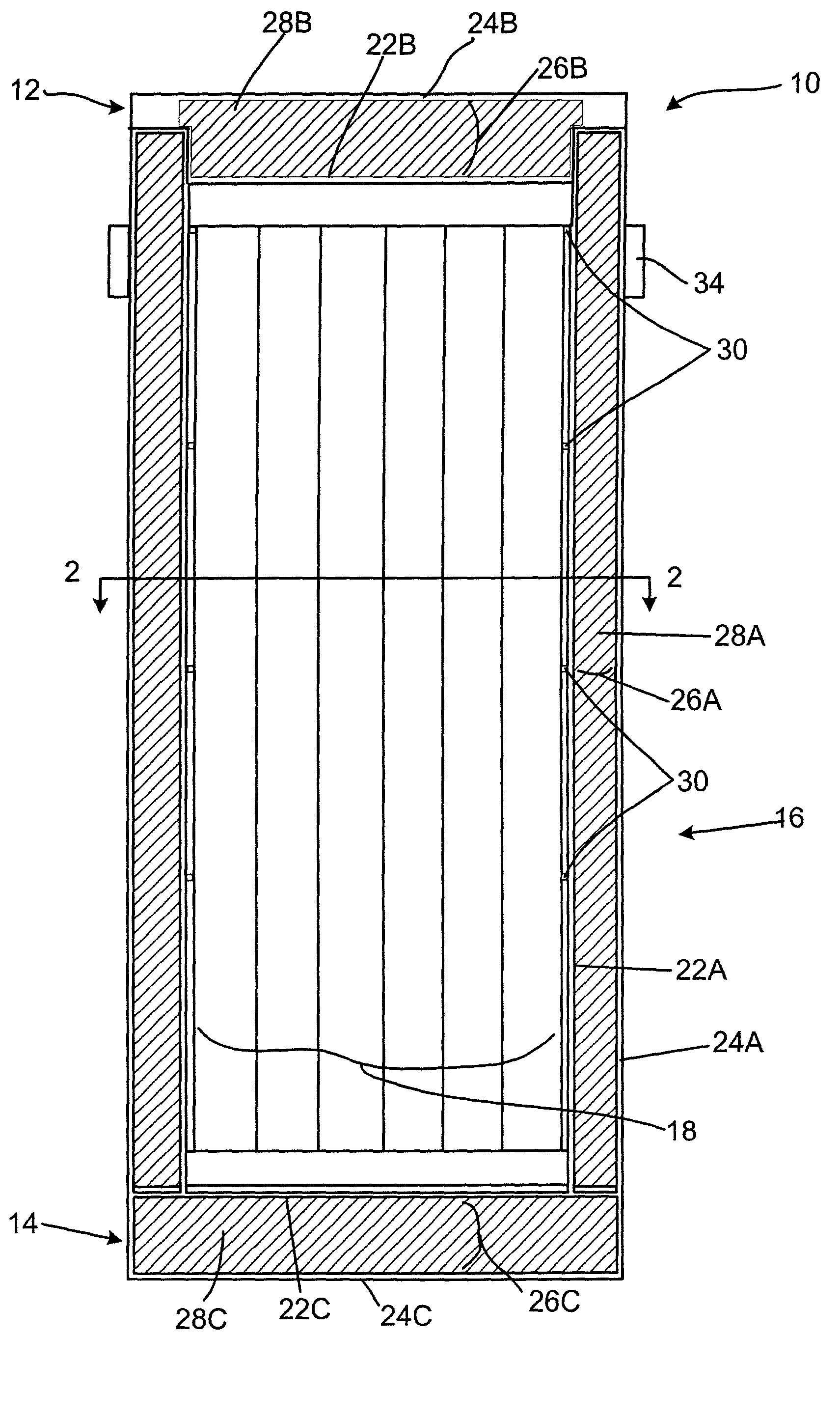
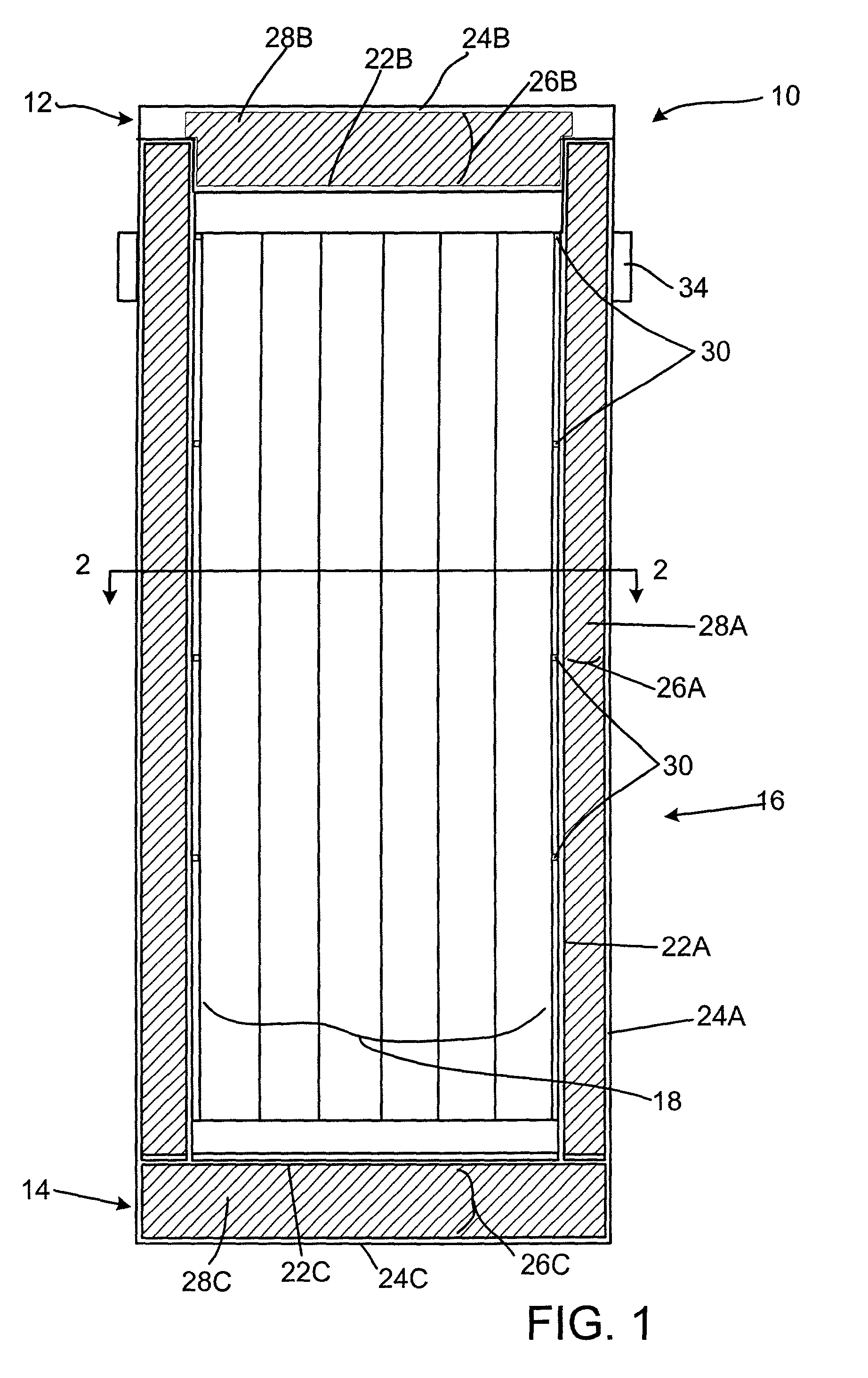
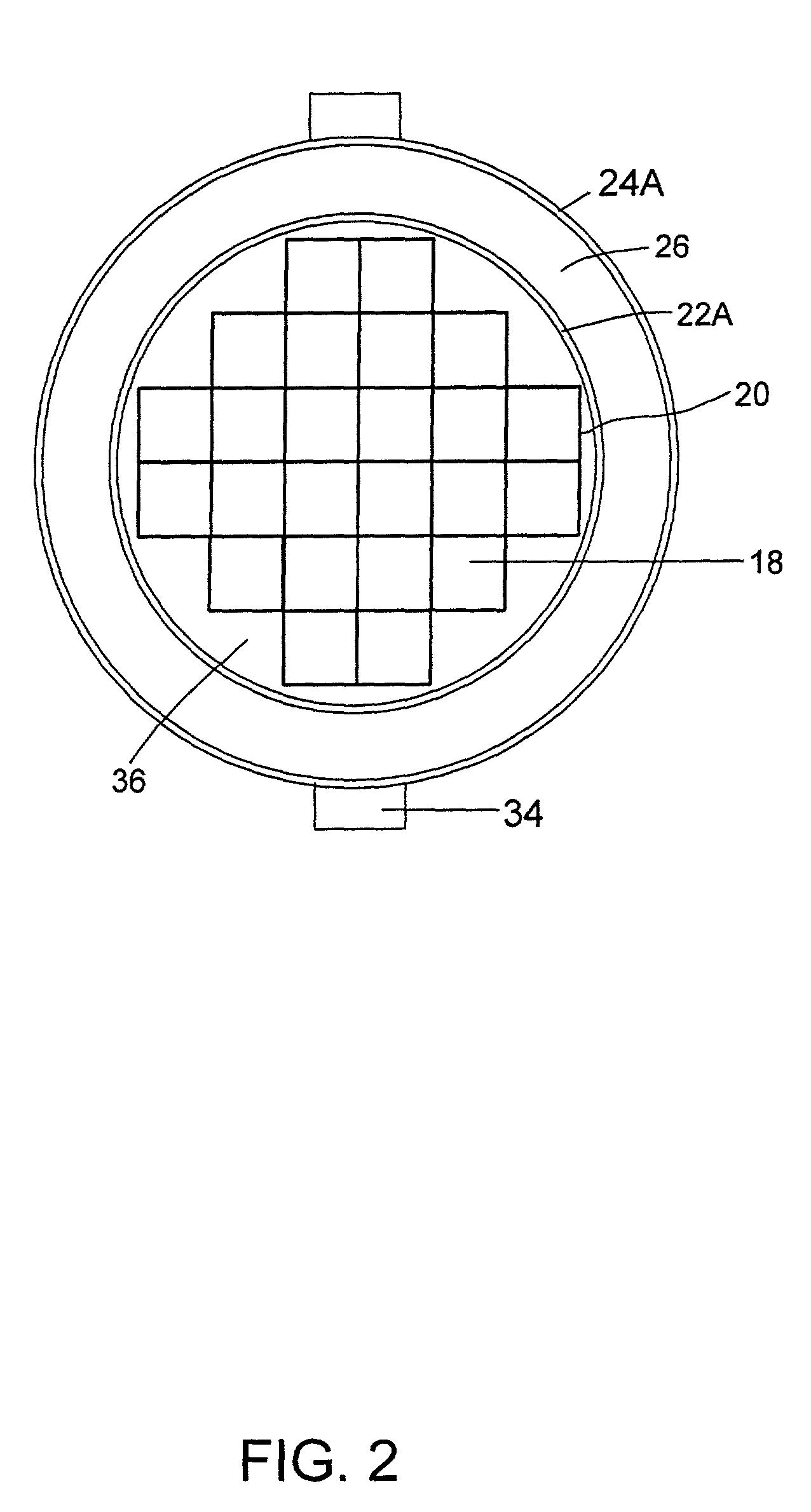
[0071]With reference now to the exemplary drawings, and particularly to FIGS. 1–2, there is shown, in cross-section, a container 10 in accordance with the present invention. The container includes a lid 12, a base 14 and a body 16 defining a central cavity 18. The container 10 is used to store waste material, including, in particular, radioactive waste materials, such as SNF. In this regard, a plurality of pressurized water reactor (“PWR”) assemblies housing waste material are fitted inside of a basket assembly 20 disposed within the container 10, as best seen in FIG. 2. The container 10 can have a variety of geometries. In the embodiment shown in FIGS. 1 and 2, the container is cylindrical, having a circular cross-section. Alternatively, the container could have a cross-section that can be square or hexagonal, among other geometries, in order to facilitate various packing and storing configurations.

[0072]The body 16 includes an inner wall 22a and an outer wall 24a thereby defining ...


PUM

PropertyMeasurementUnit
temperatureaaaaaaaaaa
timeaaaaaaaaaa

Abstract

An improved radiation shielding material and storage systems for radioactive materials incorporating the same. The PYRolytic Uranium Compound (“PYRUC”) shielding material is preferably formed by heat and/or pressure treatment of a precursor material comprising microspheres of a uranium compound, such as uranium dioxide or uranium carbide, and a suitable binder. The PYRUC shielding material provides improved radiation shielding, thermal characteristic, cost and ease of use in comparison with other shielding materials. The shielding material can be used to form containment systems, container vessels, shielding structures, and containment storage areas, all of which can be used to house radioactive waste. The preferred shielding system is in the form of a container for storage, transportation, and disposal of radioactive waste. In addition, improved methods for preparing uranium dioxide and uranium carbide microspheres for use in the radiation shielding materials are also provided.

Description

[0001]This application is a divisional of Ser. No. 08 / 826,088 filed Mar. 24, 1997, now U.S. Pat. No. 6,372,157.BACKGROUND OF THE INVENTION[0002]This present invention relates generally to radiation shielding materials, radiation shielding containers and methods for preparing the same. More particularly, the present invention relates to radiation shielding materials incorporating uranium dioxide and / or uranium carbide and containers for radioactive materials incorporating these shielding materials. This invention also relates to methods for preparing uranium dioxide and uranium carbide microspheres for use in the radiation shielding materials of the present invention.[0003]Storage, transportation, and disposal of radioactive waste, such as spent nuclear fuel (“SNF”), high level waste (“HLW”), mixed waste, and low level radiation waste is a growing problem in the United States and abroad. In 1995, the Department of Energy (DOE) estimated that the commercial SNF inventory was about 30,...

Claims


Application Information

Patent Timeline
Patent Type & Authority Patents(United States)
IPC IPC(8): C01B7/19C01B7/00G21F1/00G21F5/00G21F1/10
CPCC01B7/191G21F1/106G21F5/00
Inventor MIRSKY, STEVEN M.KRILL, STEPHEN J.MURRAY, ALEXANDER P.
Owner THE UNITED STATES AS REPRESENTED BY THE DEPARTMENT OF ENERGY
Why Eureka
Try Eureka