Brake energy recovery system

a technology of energy recovery and brakes, applied in the field of energy recovery systems, can solve the problems of difficult integration of many sensors, valves and other components into the vehicle, large quantities of expensive components to fabricate energy, and high cost of performing these functions, and achieve the effect of less expensive manufacturing and operation

Inactive Publication Date: 2011-07-07
STRAGIER MARCEL G
View PDF14 Cites 36 Cited by
  • Summary
  • Abstract
  • Description
  • Claims
  • Application Information

AI Technical Summary

Problems solved by technology

Generally, a major problem with systems that perform these functions is the complexity.
In some instances the vehicles are substantially rebuilt or large quantities of expensive components must be added to fabricate the energy saving system.
This integration of the many sensors, valves and other components into the vehicle is very expensive, labor intensive, and difficult.
This results in a very complicated and expensive system that cannot easily be installed in any or all vehicles.
That is, the vehicle itself must be a relatively expensive and complex vehicle, such as a bus or the like, to justify the installation of the very complicated and expensive system.

Method used


Image

  • Brake energy recovery system
  • Brake energy recovery system
  • Brake energy recovery system

Examples


Embodiment Construction

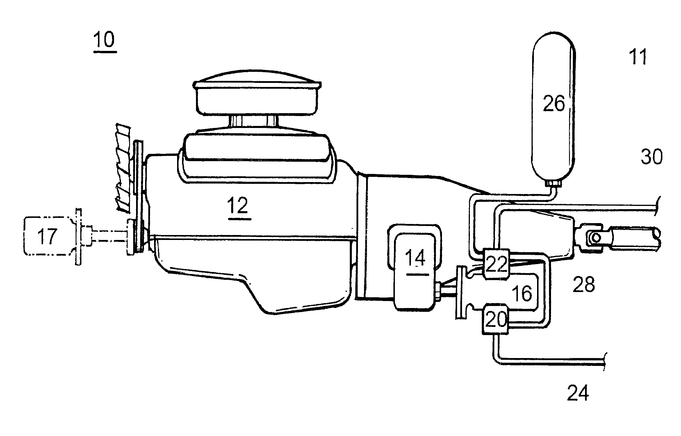
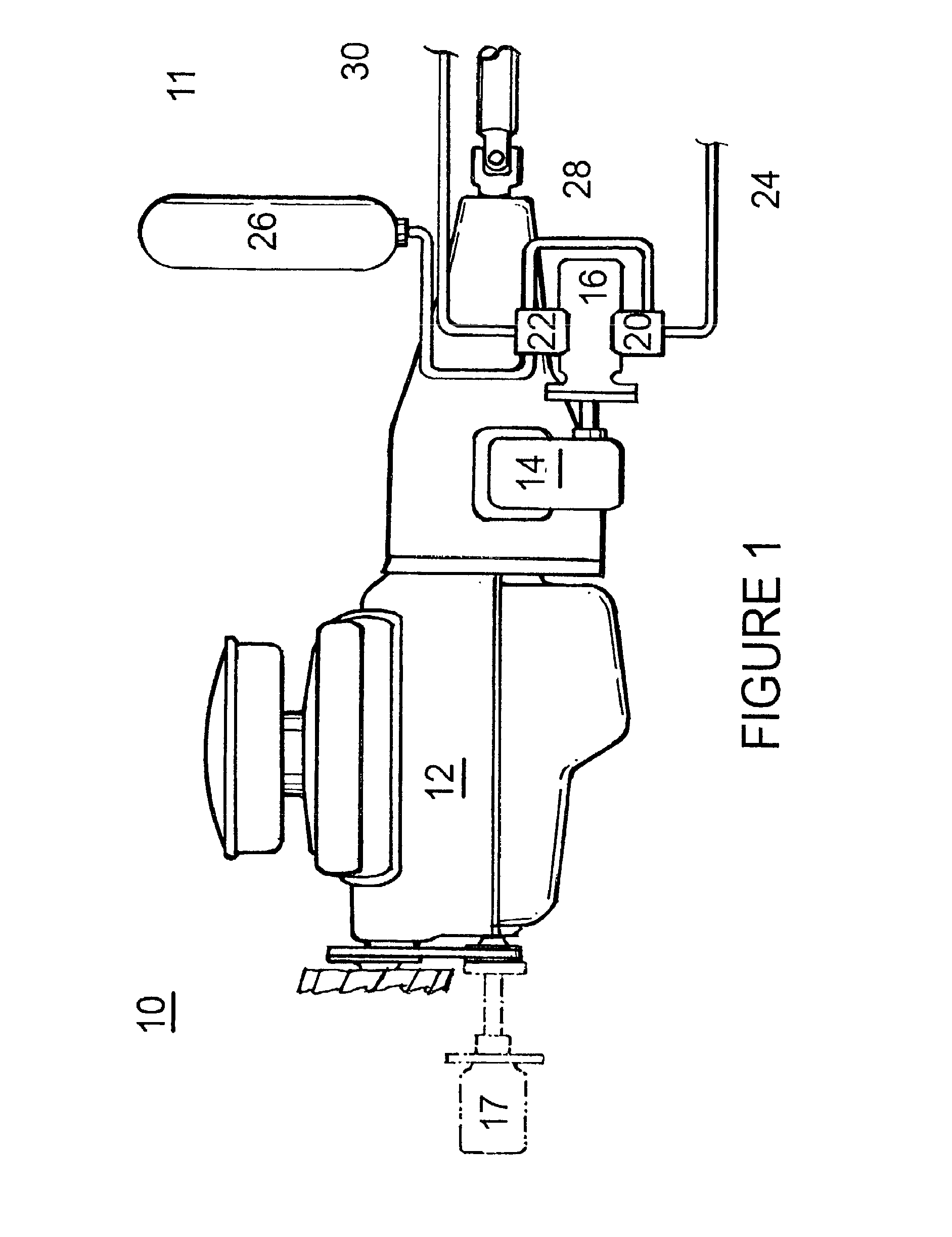
[0021]Turning now to the drawings, attention is first directed to FIG. 1, which illustrates a vehicle 10 including an engine 12 and incorporating a brake engine recovery system, generally designated 11, in accordance with the present invention. It should be understood that brake engine recovery system 11 can be initially built into vehicle 10 or vehicle 10 can be an existing vehicle that is retrofit with system 11, in either case vehicle 10 can be considered a part of brake recovery system 11 or vise versa. Many vehicles, such as refuse collection vehicles or dump trucks, are equipped with auxiliary hydraulic systems which can be easily modified to provide a limited energy recovery. In this embodiment, engine 12 has a standard power takeoff 14 associated therewith to drive a hydraulic pump 16, which may be added for purposes of this invention or may be part of a hydraulic system already built into vehicle 10 (e.g. vehicle 10 could be a refuse collection truck or the like). As the di...


PUM

PropertyMeasurementUnit
speedaaaaaaaaaa
pressureaaaaaaaaaa
speedaaaaaaaaaa

Abstract

A brake energy recovery system is used on a vehicle including an auxiliary hydraulic system. The recovery system includes a fluid accumulator and normally open and normally closed switches coupled to be closed and opened, respectively, when the brake pedal is depressed. A hydraulic charging valve is coupled to the outlet of a hydraulic pump and moveable from a neutral to a charging position when the normally open switch is closed. A motor valve is coupled to the inlet of the pump and moveable from a neutral to a driving position when the normally closed switch is in a closed position. The charging valve couples the outlet of the pump to the accumulator in the charging position and the motor valve couples the accumulator to the inlet of the pump in the driving position.

Description

TECHNICAL FIELD[0001]This invention relates to an energy recovery system and more specifically to a system in which some energy expended in a vehicle during braking is recovered.BACKGROUND ART[0002]It is well known that vehicles, such as trucks and the like, expend substantial energy when braking and accelerating. Generally, this energy is completely expended by the brakes or the engine. It is known that some of the braking energy, for example, can be bled off and stored. The stored energy can then be used in a later acceleration process. Generally, a major problem with systems that perform these functions is the complexity. In some instances the vehicles are substantially rebuilt or large quantities of expensive components must be added to fabricate the energy saving system.[0003]An example of this type of system is disclosed in U.S. Pat. No. 4,760,697, entitled “Mechanical Power Regeneration System”. In systems such as this, a microcomputer is used to receive all sensor signals an...

Claims


Application Information

Patent Timeline
Patent Type & Authority Applications(United States)
IPC IPC(8): B60T1/12F16D61/00B23P11/00
CPCB60K6/12B60T1/10Y10T29/49826Y02T10/6208Y02T10/92B60T13/686Y02T10/62
Inventor STRAGIER, MARCEL G.
Owner STRAGIER MARCEL G
Why Eureka
Try Eureka