Device and method for machining workpiece with a laser beam

Inactive Publication Date: 2011-07-07
DENSO CORP
View PDF10 Cites 14 Cited by
  • Summary
  • Abstract
  • Description
  • Claims
  • Application Information

AI Technical Summary

Benefits of technology

[0016]The laser beam blocking member is disposed such as oppose or cover the second portion. Therefore, the laser beam that passes through the hole collides with the laser beam blocking member. As a result, machining of the second portion by the laser beam is prevented.
[0017]Furthermore, the discharge path that discharges the liquid reaching the hole is provided in the laser beam blocking member. Therefore, the liquid is discharged through the discharge path in the liquid beam blocking member without remaining in the first portion. As a result, decrease in machining efficiency caused by the liquid remaining in the first portion can be prevented. Machining efficiency can be enhanced.
[0018]In a preferred example, a cross-sectional area of the discharge path is greater than an exit area of the nozzle. Therefore, the liquid can be effectively discharged through the discharge path. Machining efficiency can be further enhanced.
[0019]In another example, the holding member is configured to be capable of adjusting the angle of the workpiece and the laser beam blocking member in relation to a jetting direction of the liquid. Therefore, the workpiece can be machined even when the hole to be machined is at an angle. As a result, the present invention can be favorably applied, for example, to a hole drilling machine for machining a spray hole of a fuel injection valve.
[0020]On the other hand, according to another aspect of the present invention, a laser machining method is provided for machini

Problems solved by technology

A problem occurs in that the inner wall portion that is a non-machining portion is also machined.
However, when the laser beam blocking component is placed, obstruction of the emission of the water column by the laser bea

Method used


Image

  • Device and method for machining workpiece with a laser beam
  • Device and method for machining workpiece with a laser beam
  • Device and method for machining workpiece with a laser beam

Examples


first embodiment

[0038]First, a first embodiment will be described with reference to FIG. 1 to FIG. 7. According to the first embodiment, the laser machining device and the laser machining method of the present invention are applied to a hole drilling machine for machining a plurality of spray holes in a component (workpiece) configuring a tip of a fuel injection valve (injector) installed in a vehicle.

[0039]The spray hole of the fuel injection valve is a fine hole that is less than φ=0.3 mm and is at an angle described later. Circularity, cylindricity, and the like are required to be extremely accurate. The angle refers to an angle in relative to a direction perpendicular to the surface on which the spray hole is formed and is about 80° or less.

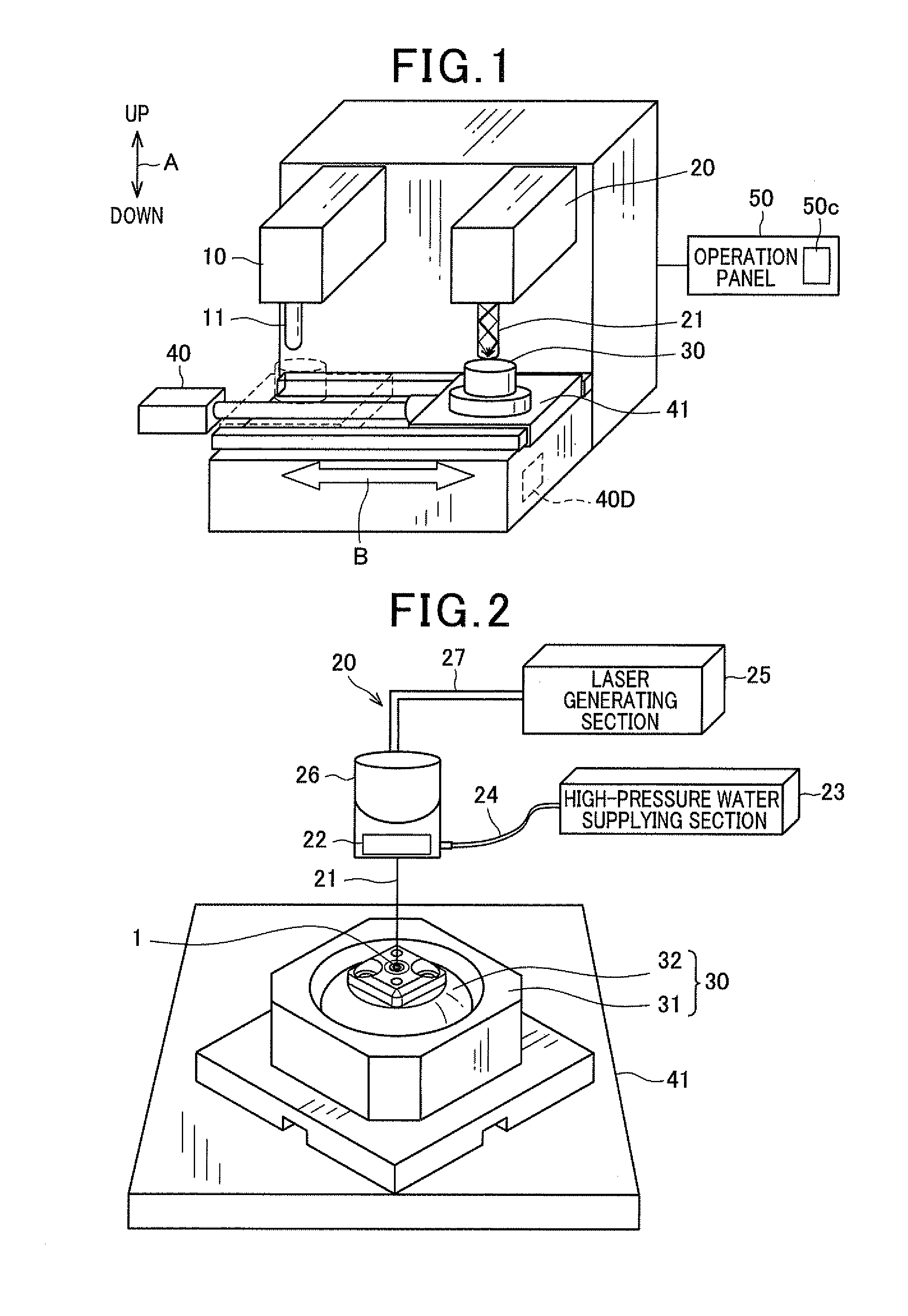
[0040]FIG. 1 is a perspective view of a rough overall configuration of the hole drilling machine. An up / down arrow A in FIG. 1 indicates the up / down direction of the hole drilling machine in a setup state.

[0041]The hole drilling machine includes a rough mach...

second embodiment

[0068]A second embodiment will be described with reference to FIG. 8A and FIG. 8B. According to the second and subsequent embodiments, constituent elements that are the same as or similar to those according to the above-described first embodiment are given the same reference numbers. Descriptions thereof are omitted or simplified.

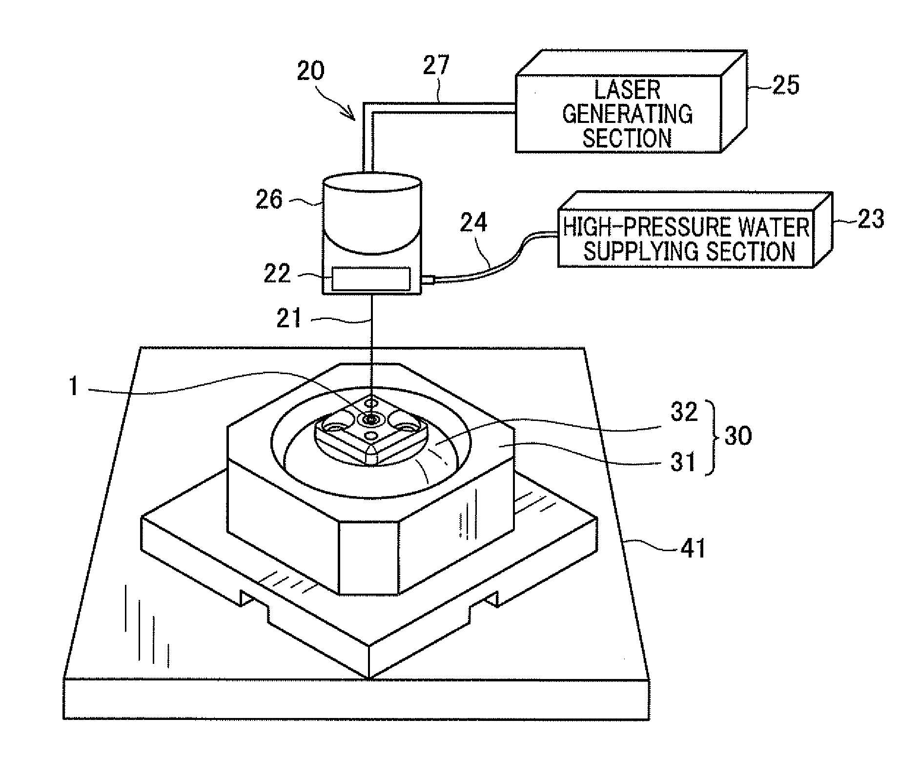
[0069]According to the above-described first embodiment, the rough machining device 10 roughly machines the hole 1c by irradiating the air laser 11 towards the workpiece 1. However, according to the second embodiment, as shown in FIG. 8A and FIG. 8B, the rough machining device 10 is configured to be capable of emitting a water-jet laser 12. In other words, the hole 1c is roughly machined by the water-jet laser 12.

[0070]A diameter (namely the diameter of a water column 12a) D of the water-jet laser 12 irradiated from the rough machining device 10 is larger than the diameter of the water-jet laser 21 from the finish-machining device 20. In other words, when t...


PUM

PropertyMeasurementUnit
Angleaaaaaaaaaa
Areaaaaaaaaaaa
Circumferenceaaaaaaaaaa

Abstract

A laser machining device machines a workpiece having a machining portion where a hole is machined and a non-machining portion positioned on an extension of the hole. The laser machining device includes a nozzle that jets a column of liquid towards the hole of the machining portion and a laser head that introduces a laser beam into the column of liquid jetted towards the hole. The workpiece is held by a holding member. A laser beam blocking member is disposed in the non-machining portion. The laser beam blocking member blocks the laser beam that passes through the hole. Furthermore, a discharge path that discharges the liquid reaching the hole is provided in the laser beam blocking member.

Description

CROSS-REFERENCE TO RELATED APPLICATION[0001]This application is related to Japanese Patent Application No. 2010-001338 filed on Jan. 6, 2010, the contents of which are hereby incorporated by reference.BACKGROUND[0002]1. Technical Field[0003]The present invention relates to a device and method for machining a workpiece using a laser beam. In particular, the present invention relates to a device and method for machining a workpiece by introducing a laser beam into a liquid column, and irradiating the workpiece with the liquid column and the laser beam using the liquid column as a guide, such as water-jet laser machining.[0004]2. Description of the Related Art[0005]In recent years, the demand for precision and operating efficiency has increased in the machining industry, such as hole drilling. For example, in the field of hole drilling, a technique is required for drilling fine holes. A machining method referred to as water-jet laser machining is used.[0006]Japanese Patent No. 3680864 ...

Claims


Application Information

Patent Timeline
IPC IPC(8): B23K26/38B23K26/08B23K26/12B23K26/382F02M61/16
CPCB23K26/388B23K26/1417B23K26/146B23K26/389
Inventor FUKUSHIMA, TAKESHISAKAI, KEIJIOOTANI, HIROYUKI
Owner DENSO CORP
Why Eureka
Try Eureka