
Scintigraphic device with high spatial resolution

a high-spatial resolution, scantigraphic technology, applied in the direction of instruments, radiation intensity measurement, material analysis, etc., can solve the problems of reducing the total flow of radiation, unsuitable for application, and lowering the overall detection efficiency, so as to achieve high spatial resolution and high acquisition efficiency. , the effect of high spatial resolution

Inactive Publication Date: 2011-07-07
CONSIGLIO NAT DELLE RICERCHE
View PDF4 Cites 5 Cited by
  • Summary
  • Abstract
  • Description
  • Claims
  • Application Information

AI Technical Summary

Benefits of technology

[0021]In particular, an object of the present invention is to make available a scintigraphic device that has high spatial resolution.
[0022]An additional object of the present invention is to make available a scintigraphic device that has high acquisition efficiency.
[0023]A further object of the present invention is to propose a scintigraphic device with high spatial resolution that has high operating flexibility, and in particular that allows to adjust resolution to a desired value.
[0024]Yet another object of the present invention is to propose a scintigraphic device with high spatial resolution that has high simplicity and ease of use, and in particular that does not require complex interventions to replace parts and / or components for use.

Problems solved by technology

In general, although increasing the length “L” determines an improvement in spatial resolution, at the same time it causes a reduction in the total flow of the radiation that reaches the detection unit, and this contributes to lower the overall detection efficiency, making it unsuitable for application in which the emission of radiation is weak.
The fact remains that, on the contrary, a reduction in the length “L” of the holes of the collimator increases detection efficiency but, disadvantageously, it significantly penalises its resolution, bringing it to values that are not often acceptable in traditional diagnostics.
However, such solutions are a compromise set at the time of construction of the device and their performance (resolution, efficiency) cannot be modified in use.
Even using more advanced phototubes like the PSPMT (position Sensitive Photo Multiplier Tube), the broadening of the charge produced in individual crystals hampers the localization of the individual scintillation events within the crystal.
In particular, within an individual crystal the possibility of distinguishing separate scintillation events entails a high complexity of the electronics linked to the method of reading the charge collected on all the anodes comprising the phototube.
However, such a replacement is very inconvenient and it entails a series of technical operations that prevent the immediate use of the equipment.
Moreover, this solution does not overcome the problem linked to the low detection efficiency and to the high acquisition times when the length of the collimator increases.

Method used


Image

  • Scintigraphic device with high spatial resolution
  • Scintigraphic device with high spatial resolution
  • Scintigraphic device with high spatial resolution

Examples


embodiment

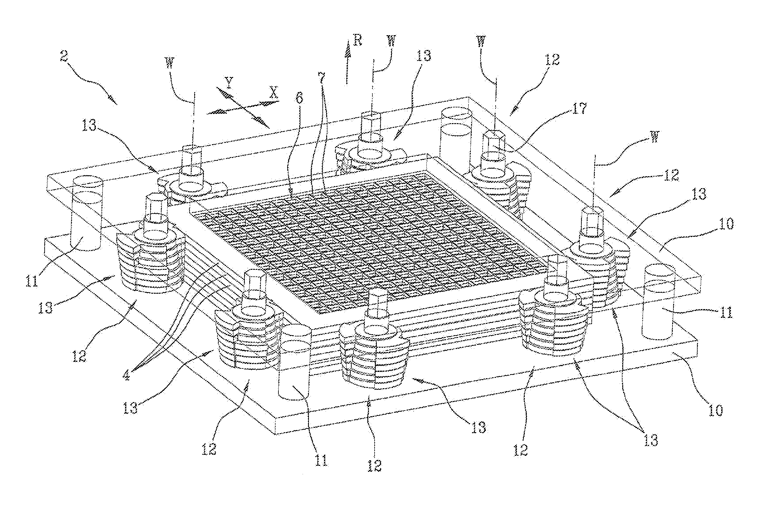
[0100]A preferred embodiment of the scintigraphic device according to the present invention is described below, with particular reference to the geometry and to the measurements of the device.

[0101]According to the embodiment in question, a matrix of 18×18 CsI (Tl) scintillation crystals is used, in which each crystal has dimensions of 2.05×2.05×5 mm3 (2.05×2.05 are the dimensions of the aforementioned receiving surface of the individual crystal, i.e. the surface oriented towards the collimator 2 and towards the ionising radiation).

[0102]The scintillation crystals are coated with a layer of 0.1 millimetres of epoxy resins on the four lateral faces and with a layer of about 1 mm of epoxy resin on the receiving surface. Said coated crystals are integrated in a metallic structure made of tungsten having separating baffles with thickness of 0.2 mm.

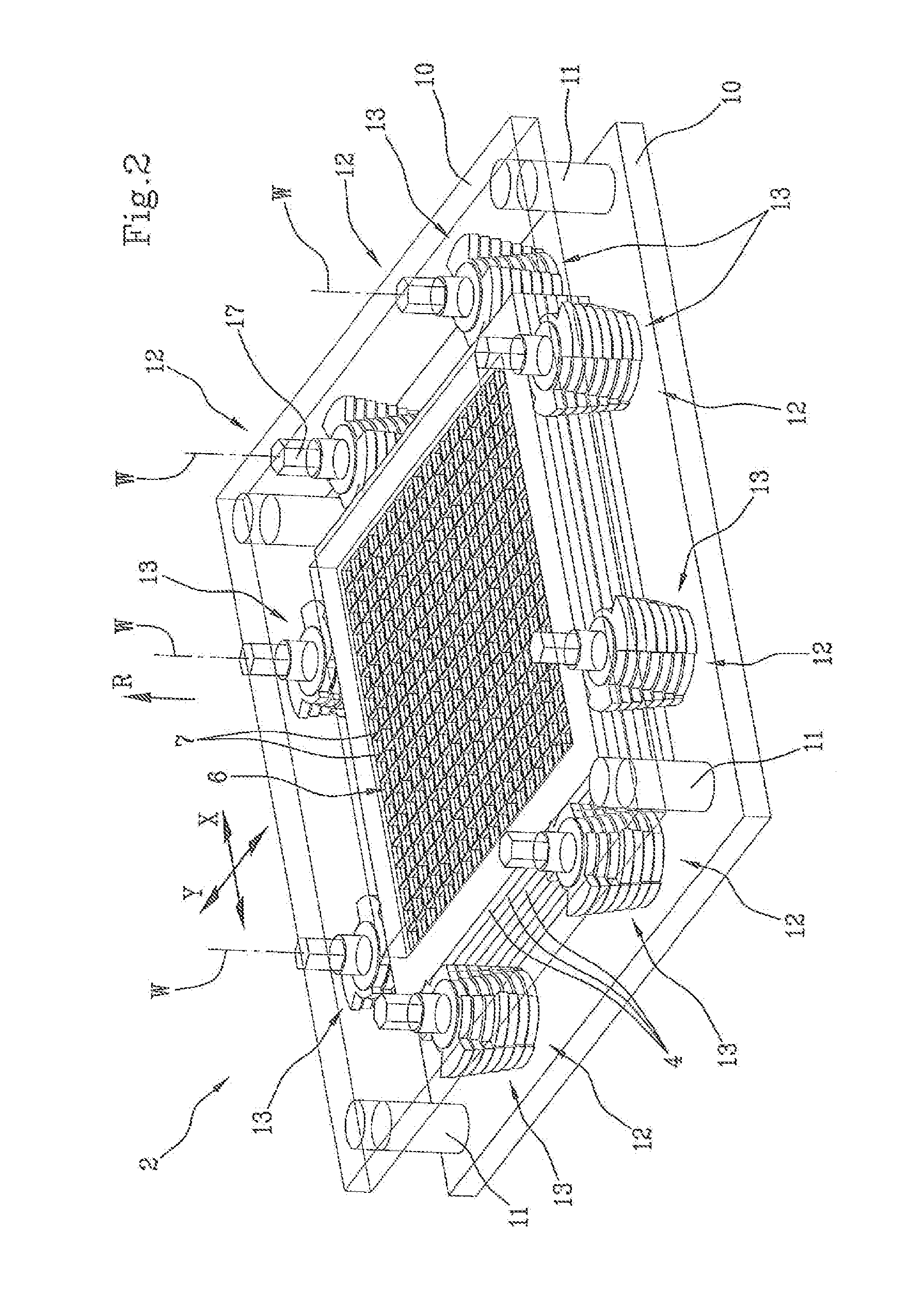
[0103]With reference to the collimator 2, seven shielding elements 4 (or grids) are provided, mutually superposed and packed by means of the ...


PUM


Abstract

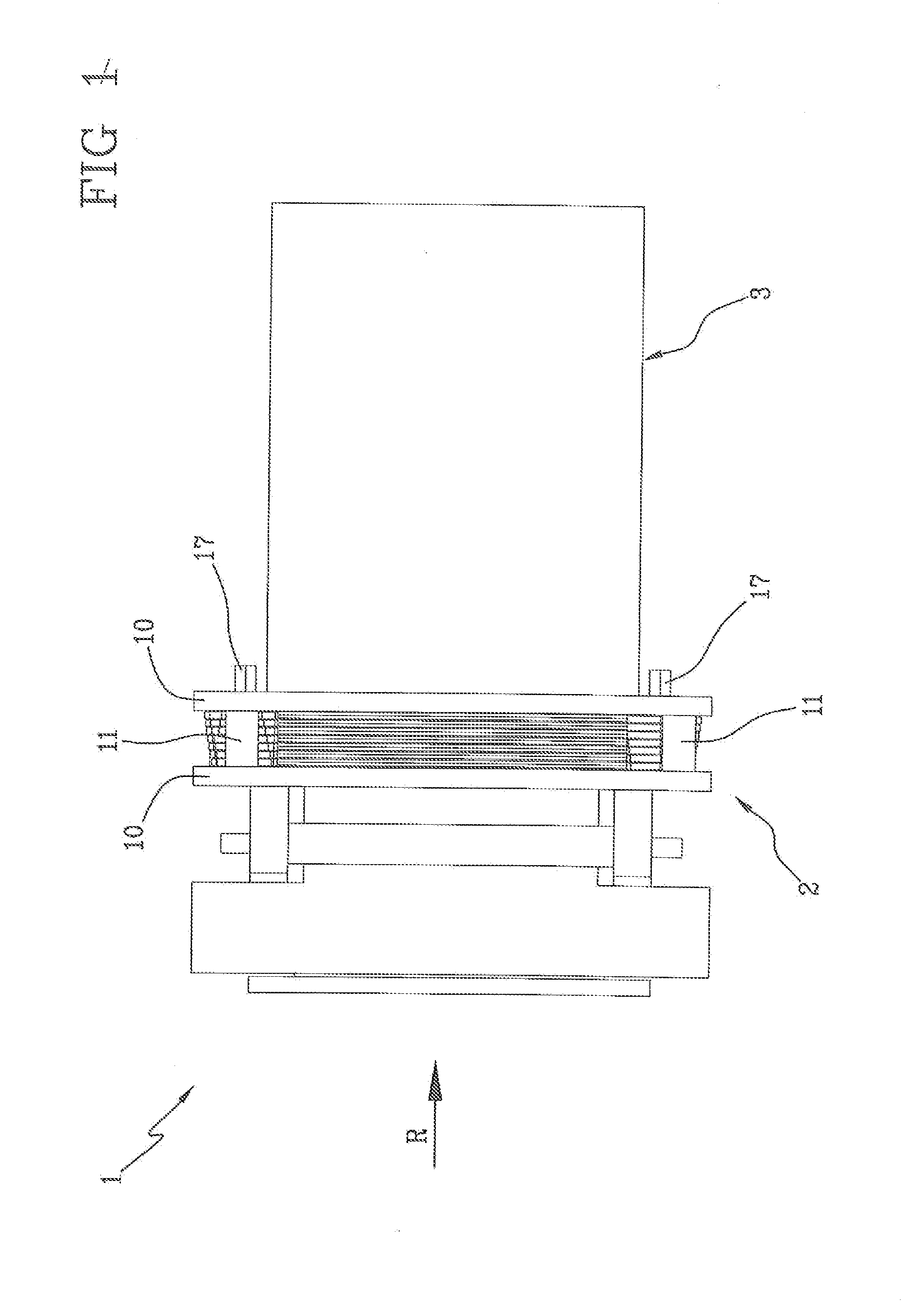
A scintillation device with high resolution includes a detection unit (3) to convert into light radiation an ionising radiation originating from a source under examination and a collimator (2) made of a material with high atomic number 3nd including a plurality of grids (4), the grids (4) co-operating with each other in mutually sliding fashion in a transverse direction to the direction of detection (R) to provide a partial coverage of the detection unit (3) in such a way as to expand and reduce in an adjustable manner a surface area of the detection unit (3) offered to the radiation.

Description

BACKGROUND OF THE INVENTION[0001]The present invention relates to a scintigraphic device with high spatial resolution.[0002]Traditional scintigraphic devices (called “gamma cameras”) essentially comprise a collimator and a detection unit.[0003]The detection unit transforms an ionising radiation (gamma rays) into an electrical signal, legible by a reading system, e.g. a computer. The electrical signal is amplified and conducted to the computer to recreate the image of the radiation source.[0004]In particular, known detection units comprise a matrix of scintillation crystals, which convert the gamma radiation into light radiation, and optoelectronic device (phototubes, photodiodes and the like) positioned downstream of the crystal matrix to transform the light radiation into the aforesaid electrical signal.[0005]Other known detection units comprise semiconductor elements which directly transform the gamma radiation into the aforementioned electrical signal.[0006]The collimator is inst...

Claims


Application Information

Patent Timeline
IPC IPC(8): G01T1/20
CPCG21K1/046G21K1/025
Inventor SOLURI, ALESSANDROMASSARI, ROBERTOSCANDELLARI, MARIACHIARATRINCI, GIULIA
Owner CONSIGLIO NAT DELLE RICERCHE
Learn More