Apparatus for fitting a shoulder prosthesis

a shoulder prosthesis and applicator technology, applied in the field of inverted or anatomical shoulder prosthesis, can solve the problems of prosthesis dislocation and pain of patients, and achieve the effects of reducing interference risk, promoting relative rotation, and increasing tension in the rotator muscles

Inactive Publication Date: 2011-07-07
TORNIER SA SAINT ISMIER
View PDF99 Cites 27 Cited by
  • Summary
  • Abstract
  • Description
  • Claims
  • Application Information

AI Technical Summary

Benefits of technology

[0007]In some embodiments, an articular face of the glenoid component occupies, relative to the scapula, a position laterally more remote than a position the articular face would occupy were the graft omitted. Removing the glenoid component laterally helps reduce risk of interference between the pillar of the scapula and the lower portion of the humeral prosthetic part cooperating with the glenoid articular face. The lateralization of the prosthetic glenoid component also helps increase tension in the rotator muscles of the shoulder and the co-adaptation vector of the deltoid muscle, which helps stabilize the prosthetic glenoid and humeral components and promote better mobility in relative rotation with a lower risk of shoulder dislocation. Furthermore, compared to typical inverted shoulder prostheses, which can be described as a medialized prostheses, lateralized prostheses according to various embodiments help restore some of the curved surface of the patient's shoulder, giving the shoulder a more pleasing appearance than the “coat hanger” appearance conferred by medialized prostheses.
[0008]Some embodiments relate to glenoid components that include adjustable length tails, or anchoring structures for use with grafts having a variety of thicknesses, according to embodiments of the present invention. For example, in some embodiments, a surgeon or other user selects a desired bone graft thickness and adjusts the overall length of an anchoring portion of the glenoid component for use with that graft thickness. By adjusting the overall length of the anchoring structures, the glenoid components are better able to facilitate lateralization of the center of rotation of the glenoid component with a secure affixation into the boney structure forming the glenoid, for example, as well as additional or alternative advantages.
[0009]According to various embodiments, complete exposure of the glenoid surface is not required and is optionally limited to positioning of the graft, promoting efficiency and reproducibility. The graft is optionally taken from the patient, although allografts, xenografts, metals, natural or synthetic materials are employed as desired. In some embodiments, the graft is taken from the upper epiphysis of the humerus of the patient's shoulder, such that the graft originates from the patient, thereby helping to limit risk of rejection, poor biological compatibility, and transmission of disease or infection, for example. Moreover, efficiencies are realized in that often times in order to implant a corresponding humeral component, the epiphysis of the patient's humerus is to be prepared by withdrawing a substantial amount of cancellous bone matter from this epiphysis which can then be used to provide the graft rather than, for example, simply discarding such bone matter. Accordingly, in some embodiments, the method includes a shaping step in which the bone matter forming the upper humeral epiphysis is shaped into a one-piece volume extending in length about an axis inclined relative to the longitudinal direction of the humerus, and a cutting step in which the volume of bone matter is removed from the humerus by cutting the humeral epiphysis transversely to the axis of this volume, the volume of bone matter thus removed forming the graft.
[0010]According to some methods, a surgical joint repair includes adjusting a length of the graft along an axis of a volume of bone matter and shaping respective longitudinal end faces of the graft to be substantially complementary to an opposing face of the glenoid component and the glenoid surface previously prepared. During the shaping step, the shaped volume of bone matter is chosen from a cylinder and a frustum of a cone, for example, centered on the axis of the shaped volume of bone matter. Before or during the shaping step, the end of the upper humeral epiphysis is resected as desired, for example, over a first plane. During the cutting step, the humeral epiphysis is optionally cut over a second plane, the first and second planes being transverse to the axis of the shaped volume of bone matter. A relative inclination of the first and second planes is adjusted as desired. During or after the shaping step, a recess is optionally formed that is centered on the axis of the volume of bone matter in the humeral epiphysis. In some embodiments, the glenoid component is anchored in the glenoid surface through the recess and, before carrying out the shaping step, a marker pin is inserted into the humeral epiphysis, thereby allowing, during the shaping step, positioning of the axis of the volume of bone matter relative to the humerus.
[0012]According to still other embodiments, the graft includes a purée of bone substance (e.g, originating from the patient, in such as from the upper epiphysis of the humerus, or from another, source, such as a synthetic or metallic source). In some embodiments, the purée of bone substance is advantageously used with a protective structure, such as a lattice shaped into a cage that is filled with the purée. The lattice cage optionally facilitates good exchange of biological flows between the purée forming the graft and the surrounding tissues of the shoulder.

Problems solved by technology

This interference between the humeral prosthetic part and the scapula limits the range of the adduction movement and may cause pain to the patient or even lead to the prosthesis becoming dislodged, in particular by osteolysis of the scapula.

Method used


Image

  • Apparatus for fitting a shoulder prosthesis
  • Apparatus for fitting a shoulder prosthesis
  • Apparatus for fitting a shoulder prosthesis

Examples


Embodiment Construction

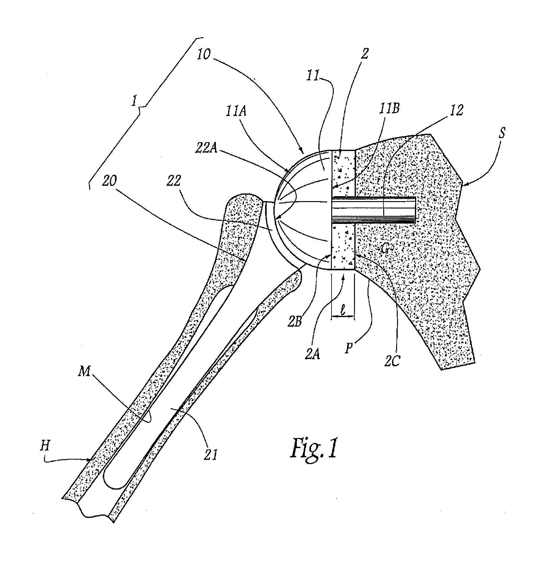
[0047]FIG. 1 shows a shoulder prosthesis 1 comprising a glenoid component 10 and a humeral component 20, respectively implanted in the scapula S and the humerus H of a patient's shoulder. The glenoid components shown herein are illustrated schematically. The method and apparatus of the various embodiments disclosed herein may be used with a variety of other glenoid components, such as for example those disclosed in U.S. Pat. Nos. 7,033,396; 6,953,478; 6,761,740; 6,626,946; 5,702,447 and U.S. Publication Nos. 2004 / 0220673; 2005 / 0278030; 2005 / 0278031; 2005 / 0278032; 2006 / 0020344, which are hereby incorporated by reference.

[0048]The glenoid component 10 comprises a head 11, also described as a head structure, which has, on the side opposing the glenoid surface G of the scapula S, a convex articular surface 11A, also described as a face, of generally hemispherical shape and, on the side turned toward the glenoid surface, an opposing face 11B. In the example considered in the figures, thi...


PUM

PropertyMeasurementUnit
thickaaaaaaaaaa
lengthaaaaaaaaaa
strength-to-weight ratioaaaaaaaaaa

Abstract

Method and set of surgical instruments for fitting a shoulder prosthesis, and the shoulder prosthesis. The proposed method seeks to interpose a bone graft between the previously prepared glenoid surface of a scapula of a patient's shoulder and the face of a glenoid prosthetic component opposite the articular surface. The set of instruments permit the bone graft to be taken from the upper epiphysis of the humerus, either in situ or ex vivo.

Description

CROSS REFERENCE TO RELATED APPLICATIONS[0001]The present application is a continuation-in-part application of U.S. patent application Ser. No. 12 / 020,913 filed Jan. 28, 2008, entitled “Method and Apparatus for Fitting a Shoulder Prosthesis,” which claims priority to French Application No. 0700622, entitled “Méthode et ensemble d'instrumentation chirurgicale pour poser une prothèse totale d'épaule inversée, et prothèse correspondante,” filed Jan. 30, 2007 and also claims the benefit of U.S. Provisional Application Ser. Nos. 60 / 888,437 filed Feb. 6, 2007, 60 / 971,762 filed Sep. 12, 2007 (both entitled “Method and Apparatus for Fitting an Inverted Shoulder Prosthesis”) and U.S. Provisional Application Ser. No. 61 / 015,042, entitled “Intra-Articular Joint Replacement,” filed Dec. 19, 2007, the complete disclosures of each of which are hereby incorporated by reference.FIELD OF THE INVENTION[0002]The present invention relates to an inverted or an anatomical shoulder prosthesis including a g...

Claims


Application Information

Patent Timeline
Patent Type & Authority Applications(United States)
IPC IPC(8): A61F2/40
CPCA61F2002/30677A61F2002/2817A61F2/4081A61B2017/1778A61F2/30767A61F2002/2835A61F2/28A61F2002/302A61F2/40A61B17/1684A61F2220/005A61F2002/30878A61F2002/30736A61F2002/4022A61F2230/0069A61F2002/30225A61F2002/30911A61F2002/30433A61F2230/0065A61F2002/30884A61F2/4644A61B17/1635A61F2310/00796A61F2220/0041A61F2/30734A61B17/1615A61F2002/4085A61B17/1637A61F2002/30448A61F2310/00359A61B17/86A61B17/1778A61F2/4003A61F2/4612
Inventor BOILEAU, PASCALWALCH, GILLESGOSSET, IRENEDERANSART, PIERRIC
Owner TORNIER SA SAINT ISMIER
Why Eureka
Try Eureka