
Falling prevention controlling device and computer program

a controlling device and computer program technology, applied in adaptive control, process and machine control, instruments, etc., can solve the problems of increasing the inclined angle and the inability to effectively perform the control of falling prevention, increasing the noise and the offset, and preventing the falling in the pitch direction. , to achieve the effect of simple configuration and preventing the falling in the pitch direction

Active Publication Date: 2011-07-07
MURATA MFG CO LTD
View PDF24 Cites 18 Cited by
  • Summary
  • Abstract
  • Description
  • Claims
  • Application Information

AI Technical Summary

Benefits of technology

To overcome the problems described above, preferred embodiments of the present invention provide a falling prevention controlling device and a computer program that, with a simple configuration, can precisely correct the inclination in a pitch direction with respect to the balanced state while securing movement in the front-back direction, without accumulating a noise and an offset, and prevent falling in the pitch direction. A falling prevention controlling device according to a preferred embodiment of the present invention preferably includes a wheel which rotates and moves in a front-back direction, and a main body which is connected to a rotation axis of the wheel and which swings in a pitch direction and a roll direction above the wheel. The main body preferably includes a pitch angular velocity sensor arranged to detect a pitch angular velocity which is an angular velocity of an inclined angle in the pitch direction, a pitch motor arranged to rotate the wheel in conjunction with a rotation of the wheel, and a pitch rotation sensor arranged to detect a rotation position or a rotation velocity of the pitch motor. Preferably, the falling prevention controlling device corrects an inclination of the main body in the pitch direction by utilizing a reaction torque resulting from the rotation of the wheel and includes an advance / retreat command receiving unit arranged to receive an advance or a retreat command of the wheel, a target pitch angle calculating unit arranged to calculate a target pitch angle which is a target inclined angle in the pitch direction, based on a rotation velocity deviation in the pick direction calculated from the received advance or retreat command and the rotation angle detected in the pitch rotation sensor, a pitch inclined angle estimating unit arranged to estimate a pitch inclined angle which is an angle at which the main body is inclined in the pitch direction with respect to a balanced state, from the pitch angular velocity detected in the pitch angular velocity sensor and a pitch torque command generated based on the target pitch angle and given to the pitch motor, and a pitch torque command generating unit arranged to generate the pitch torque command based on the target pitch angle and the pitch inclined angle.
Consequently, according to the configuration described above, it is possible to precisely estimate the pitch inclined angle at which the main body is inclined in the pitch direction with respect to the balanced state, and the pitch angular velocity of the pitch angular velocity sensor is not integrated and therefore a calculation error of the target pitch angle due to the accumulation of a noise and an offset is not produced, so that it is possible to precisely correct the inclination in the pitch direction with respect to the balanced state by utilizing a reaction torque resulting from a rotation of a wheel, and prevent falling in the pitch direction. Further, by receiving an advance or a retreat command of a wheel, and calculating a target pitch angle based on a rotation velocity deviation in the pick direction calculated from the received advance or retreat command and the rotation angle detected in the pitch rotation sensor, it is possible to correct the inclination in the pitch direction while securing the rotation velocity for the commanded movement. Furthermore, it is possible to simplify and miniaturize a falling prevention controlling device with a simple configuration which does not additionally require, for example, an acceleration sensor, and in which an angular velocity sensor is only added in addition to, for example, a motor required to drive a wheel.

Problems solved by technology

However, with the method of integrating an angular velocity using an angular velocity sensor, when an angular velocity output detected by the angular velocity sensor includes a noise and an offset, the noise and the offset are amplified by integration.
The amplified noise and offset accumulate, and therefore, there is a problem in that a shift from a target value increases and the estimation of an inclined angle and control of falling prevention cannot be effectively performed.
In contrast, with the method of detecting the inclination using a weight, the inclination cannot be reflected instantly due to the influence of the gravity, and therefore, the responsiveness of this method is poor and the inclination is detected in the vertical direction.
Thus, there is a problem in that the inclination with respect to the balanced state cannot be detected.
However, with the monocycle of Kasai, although the inclination with respect to the gravity direction (vertical direction) is measured by acceleration sensors, the balanced state in the vertical direction is not necessarily maintained in the front-back direction similar to the above left-right direction.
Therefore, there is a problem in that, when the balanced state is not maintained in the vertical direction, the inclined state cannot be corrected to the balanced state.
Further, two acceleration sensors are required in addition to a gyro sensor to estimate the inclination, and therefore, there is a problem in that it is difficult to simplify and miniaturize a configuration of a falling prevention controlling device.

Method used


Image

  • Falling prevention controlling device and computer program
  • Falling prevention controlling device and computer program
  • Falling prevention controlling device and computer program

Examples


Embodiment Construction

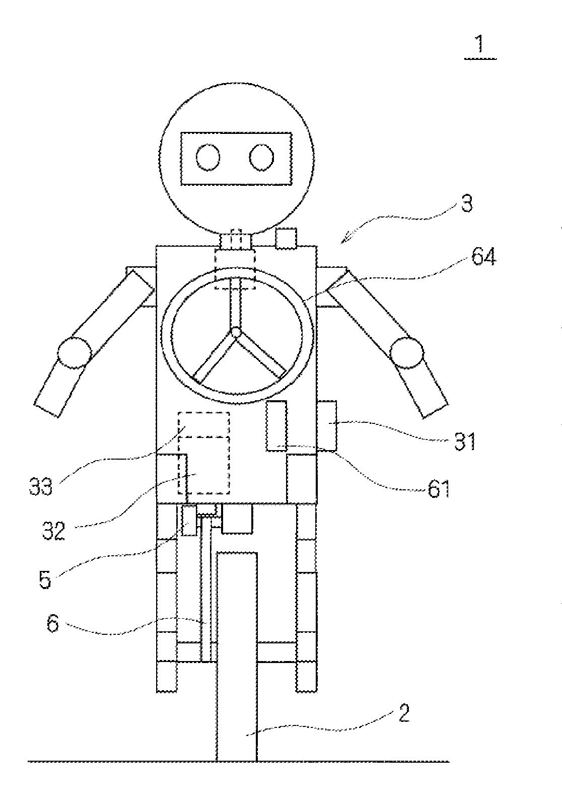
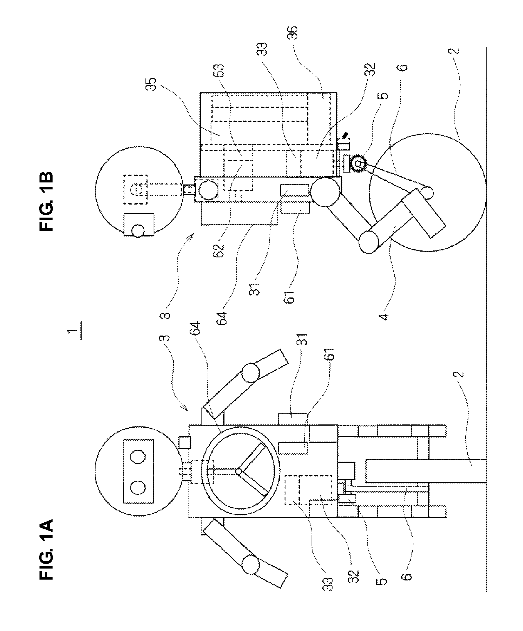
Hereinafter, examples will be described with reference to the drawings in which a falling prevention controlling device according to preferred embodiments of the present invention is preferably applied to a monocycle robot which moves back and forth without falling due to a rotation of a monocycle while the main body mounted on the monocycle swings.

FIGS. 1A and 1B are a front view and a lateral side view schematically illustrating a configuration of a monocycle robot to which a falling prevention controlling device according to a preferred embodiment of the present invention is applied.

FIG. 1A is a front view and FIG. 1B is a right side view. The falling prevention controlling device according to the present preferred embodiment functions to prevent the monocycle robot from falling in the pitch direction and in the roll direction.

As illustrated in FIGS. 1A and 1B, a monocycle robot 1 preferably includes a wheel 2 which rotates and moves in the front-back direction, and a main body 3...


PUM


Abstract

A falling prevention controlling device includes a wheel, and a main body arranged to swing in a pitch direction and a roll direction above the wheel, an advance / retreat command receiving unit arranged to receive an advance or a retreat command of the wheel, a target pitch angle calculating unit arranged to calculate a target pitch angle based on the received command and a rotation velocity deviation in the pitch direction derived from the detected rotation angle, a pitch inclined angle estimating unit arranged to estimate a pitch inclined angle with respect to a balanced state, from the detected pitch angular velocity and a pitch torque command generated based on the target pitch angle, and a pitch torque command generating unit arranged to generate the pitch torque command based on the target pitch angle and the pitch inclined angle.

Description

BACKGROUND OF THE INVENTION1. Field of the InventionThe present invention relates to a falling prevention controlling device and a computer program to prevent even a monocycle from falling in a pitch direction.2. Description of the Related ArtConventionally, when, for example, two-wheeled vehicles and two-legged walking robots move, a main body swings in a roll direction, which has an axis extending in a substantially front-back direction, and therefore, it is necessary to control an operation to move or stop the vehicle or robot without falling by controlling the balance in the roll direction. To prevent falling in the roll direction, it is necessary to accurately detect the inclination in the roll direction. A method of detecting the inclination of the body to control the balance in the roll direction includes, for example, a method of detecting an angular velocity using an angular velocity sensor and estimating the inclination by integrating the detected value, and a method of de...

Claims


Application Information

Patent Timeline
IPC IPC(8): G01M1/38G05B13/00
CPCB62K1/00B62K3/007G05D1/0891A63H17/25B25J5/007B62K17/00B60L3/0038B60L15/20B60L2200/14B60L2240/423B60L2260/34B60L2260/44B62K11/007Y02T10/72Y02T10/64B25J5/00
Inventor TSUJI, SHIGERUFUKUNAGA, SHIGEKINAMURA, MITSUHIROKAWAI, KOJISHIRATO, KENICHI
Owner MURATA MFG CO LTD
Learn More