
Method for reducing urea deposits in an aftertreatment system

a technology of aftertreatment system and urea, which is applied in the direction of exhaust treatment electric control, electrical control, machines/engines, etc., can solve the problems of reducing nosub>x /sub>efficiency, urea deposits, and reducing nosub>x /sub>efficiency, so as to facilitate the reduction of nox and reduce emissions , the effect of reducing nox conversion efficiency

Active Publication Date: 2011-07-14
FORD GLOBAL TECH LLC
View PDF14 Cites 45 Cited by
  • Summary
  • Abstract
  • Description
  • Claims
  • Application Information

AI Technical Summary

Benefits of technology

The patent describes a method for controlling a aftertreatment system in a vehicle exhaust that reduces urea deposits and increases NO conversion efficiency. The method involves adjusting the amount of urea injected into the system based on factors such as engine soot production and exhaust temperature. By controlling the urea injection, the system can better manage the formation of urea deposits and reduce the amount of white smoke in the exhaust. This can improve the efficiency of the aftertreatment system and reduce the amount of urea consumed.

Problems solved by technology

An injection amount of urea that is too low may result in a NOX conversion efficiency that is too low to meet regulation standards.
On the other hand, an injection amount of urea that is too high may result in urea deposits in the system which may also decrease NOX efficiency and increase urea slip, as well as generate increased white smoke in the exhaust at high temperatures when the deposit is decomposed and released.
Further, injection of too much urea may increase urea consumption thereby reducing urea economy.

Method used


Image

  • Method for reducing urea deposits in an aftertreatment system
  • Method for reducing urea deposits in an aftertreatment system
  • Method for reducing urea deposits in an aftertreatment system

Examples


Embodiment Construction

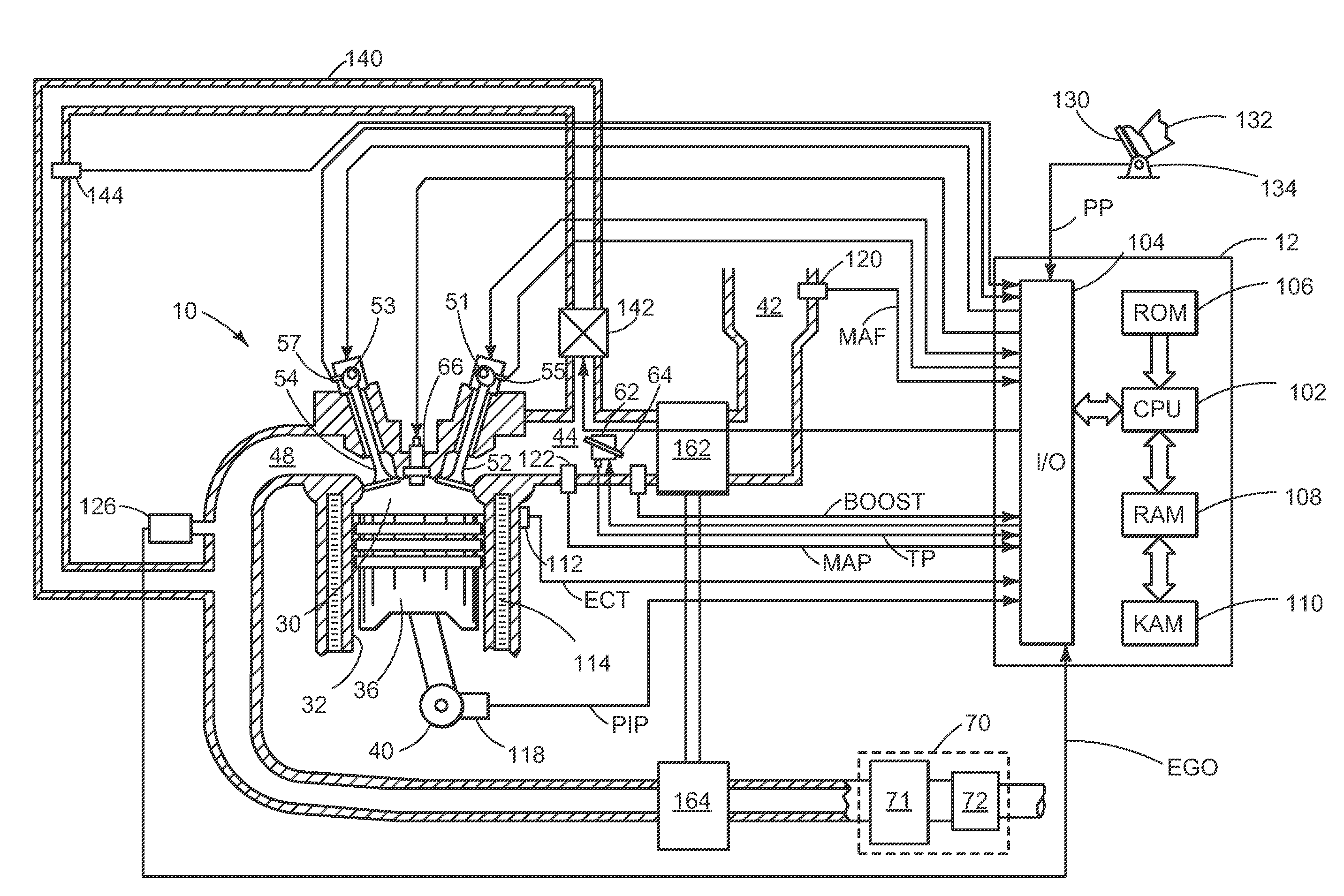
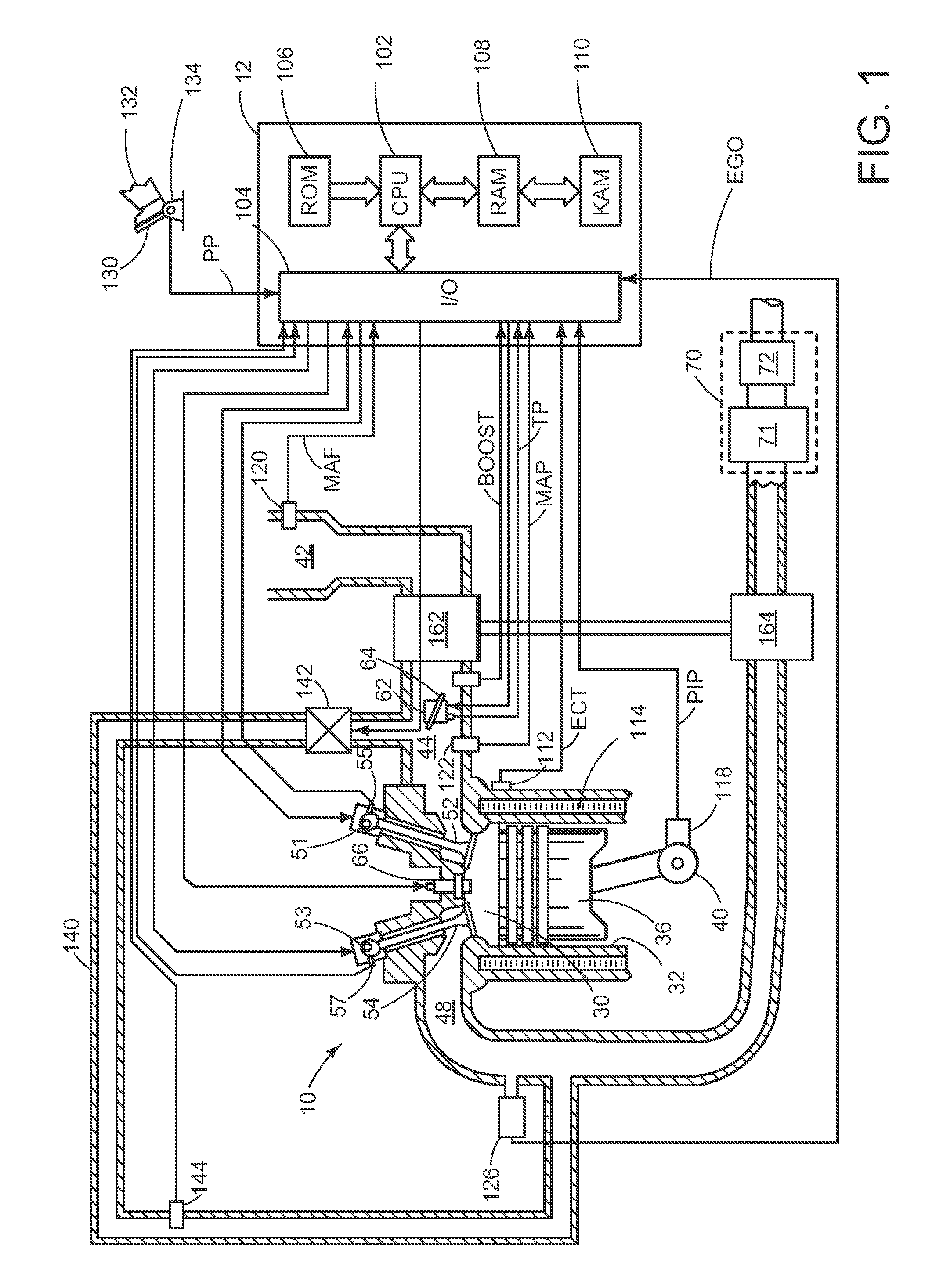
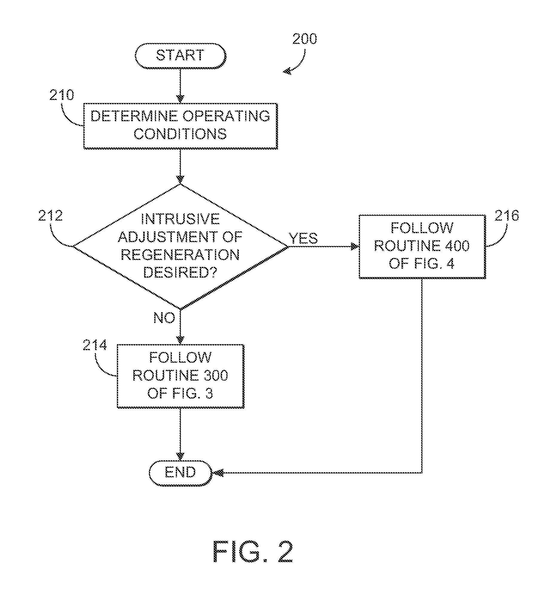
[0013]The following description relates to a method for controlling an aftertreatment system which includes a urea injection system, a selective catalytic reduction (SCR) catalyst and a particulate filter (PF), and particularly relates to addressing issues of urea deposit. Depending on operating parameters such as exhaust temperature, some of the urea may be deposited on the SCR catalyst instead of being decomposed and absorbed (e.g., stored) by the catalyst for NOX reduction. In a first regeneration mode, when an accumulated amount of urea deposit is less than a threshold amount, for example, a threshold amount of urea injected to the SCR is adjusted (e.g., limited to a lower level) based, in part, on an amount of soot generated by the engine. In a second regeneration mode, when the accumulated amount of urea deposit is greater than the threshold amount, for example, the threshold amount of urea injected to the SCR is adjusted (e.g., limited to a higher level) again based, in part,...


PUM


Abstract

Various systems and methods are described for controlling a diesel aftertreatment system coupled to an exhaust system of an engine which includes a selective catalytic reduction (SCR) catalyst and a diesel particulate filter (PF). In one example, a threshold amount of urea injected to the SCR catalyst is adjusted based on an amount of soot generated by the engine and the total amount of urea injected to the SCR catalyst is limited by the threshold. For example, when the amount of soot generated by the engine is below a first threshold amount, the threshold amount of urea injection is reduced. When the amount of soot generated by the engine is above a second threshold amount, which is greater than the first threshold amount, the threshold amount of urea injection is increased.

Description

TECHNICAL FIELD[0001]The present application relates to reducing an accumulated amount of urea deposited in an aftertreatment systemBACKGROUND AND SUMMARY[0002]Diesel vehicles are equipped with an aftertreatment system which may include, for example, one or more of each of a selective catalytic reduction (SCR) system and a diesel particulate filter in order to reduce emissions. Such an aftertreatment system may utilize the injection of a reductant such as urea to facilitate the reduction of NOX, for example. An injection amount of urea that is too low may result in a NOX conversion efficiency that is too low to meet regulation standards. On the other hand, an injection amount of urea that is too high may result in urea deposits in the system which may also decrease NOX efficiency and increase urea slip, as well as generate increased white smoke in the exhaust at high temperatures when the deposit is decomposed and released. Further, injection of too much urea may increase urea consu...

Claims


Application Information

Patent Timeline
Patent Type & Authority Applications(United States)
IPC IPC(8): F01N9/00F01N3/20
CPCF01N3/023F01N3/035F01N3/2073F01N3/208Y02T10/24F01N2610/146F01N2900/0411F01N2900/1606F01N2610/02F02D41/0245F02D41/027F02D41/029F02D2200/0812Y02A50/20Y02T10/12
Inventor CHEN, KEVIN
Owner FORD GLOBAL TECH LLC
Learn More