Solar Trough Field System

Inactive Publication Date: 2011-07-14
HSE HITIT SOLAR ENERJI ANONIM SIRKETI
View PDF7 Cites 18 Cited by
  • Summary
  • Abstract
  • Description
  • Claims
  • Application Information

AI Technical Summary

Benefits of technology

[0024]Another object of the invention is to use a vertical loop between successive parabolic troughs (located at the discharge side of the parabolic trough units) to provide the heat expansion factor for the Heat Receiving Pipe and also to prevent the remained water (which has not evaporated) from passing to the next pipe and so it remains in the heat receiving pipe until it becomes steam.
[0025]Another object of the invention is to solve the wind load problem and to prevent the mirror breakage problem caused by the wind load, by using a wind breaker to surround the Solar Trough Field to deflect the wind abo

Problems solved by technology

The existing Solar through Field type of Thermal Energy technologies have some design problems which cause thermodynamic efficiency losses and increase fabrication, installation, operation and maintenance costs.
These design problems are:
The most fundamental problem of this system is that the thermal receiver tubes which are made of a fragile material are movable.
The thermal receiver tubes which are subjected to the torque loads have a higher possibility of breaking.
On the other hand, it is understood that the flexible hose connection is not a safe system since the temperature of the fluid which is transferred within the thermal receiver tube is 300-500° C. In addition, it has been obtained from the field observations that the truss structure, which supports the parabolic mirrors, is also weak against the torque and the moment loads acting due to the drive unit of the system and the wind.
Because of these loads, the parabolic reflectors are frequently broken, thus causing the operating costs to increase.
Even though hot oil does not have the dynamics of the steam, these hoses st

Method used


Image

  • Solar Trough Field System
  • Solar Trough Field System
  • Solar Trough Field System

Examples


Embodiment Construction

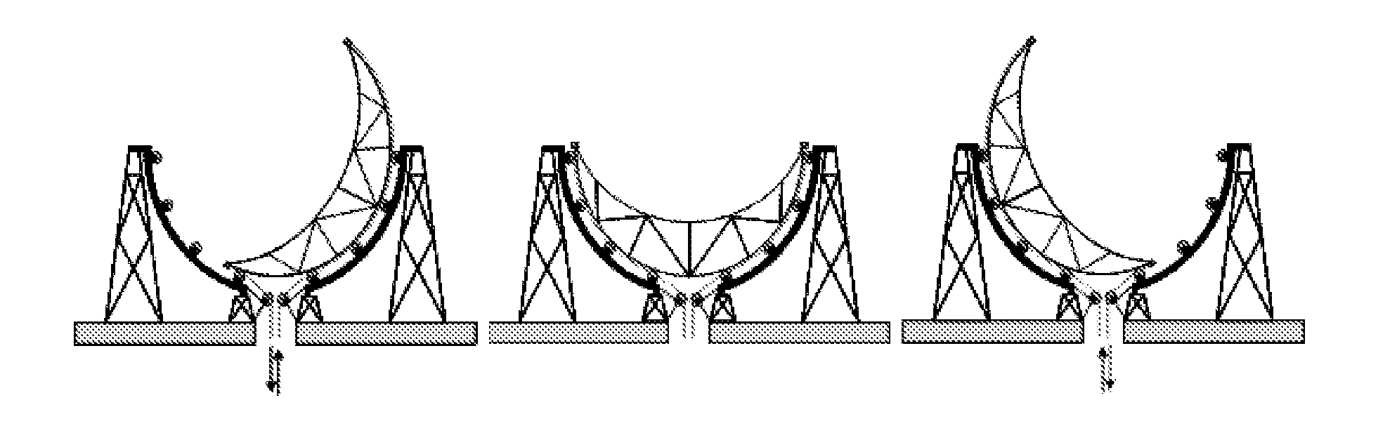
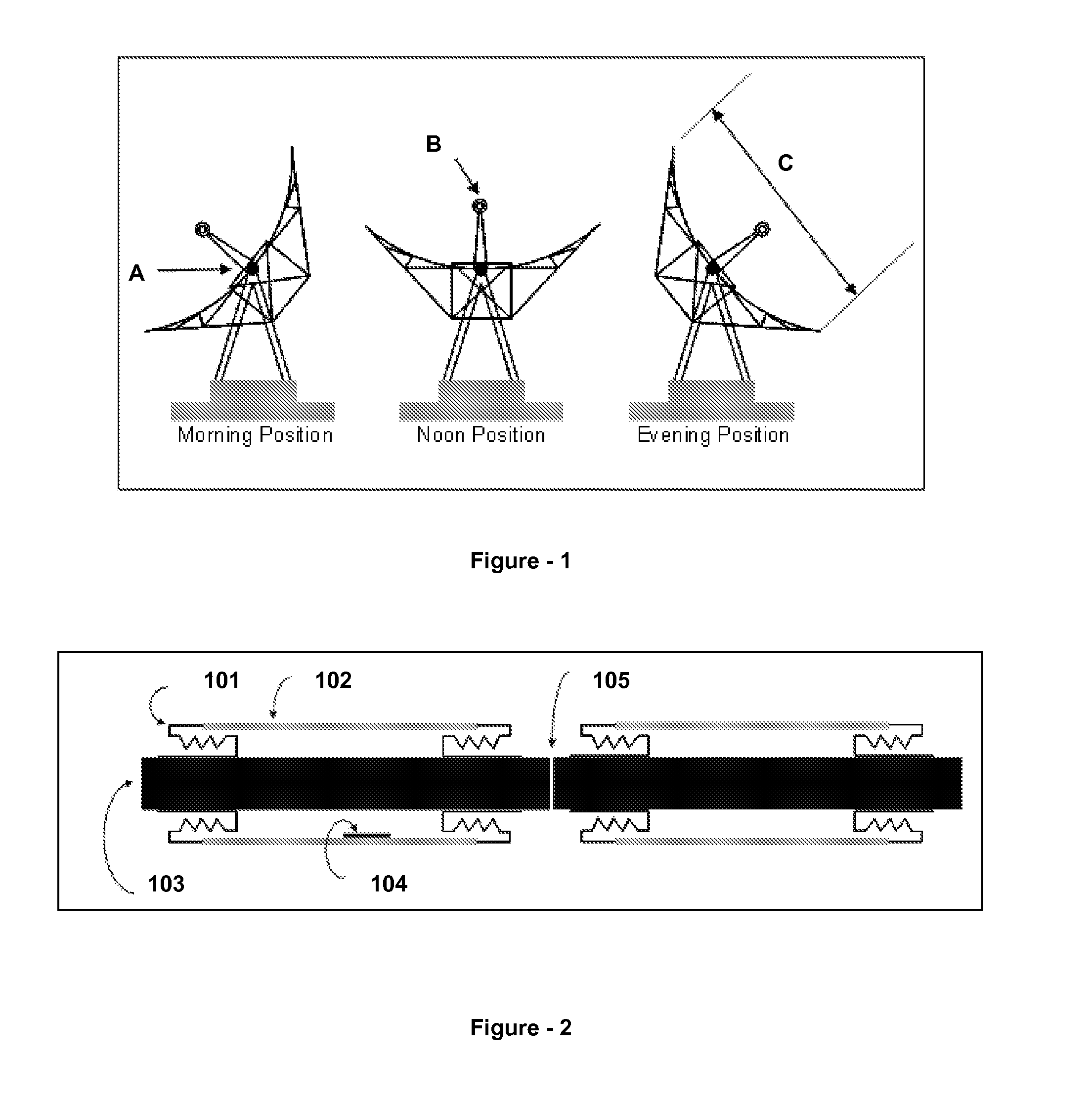
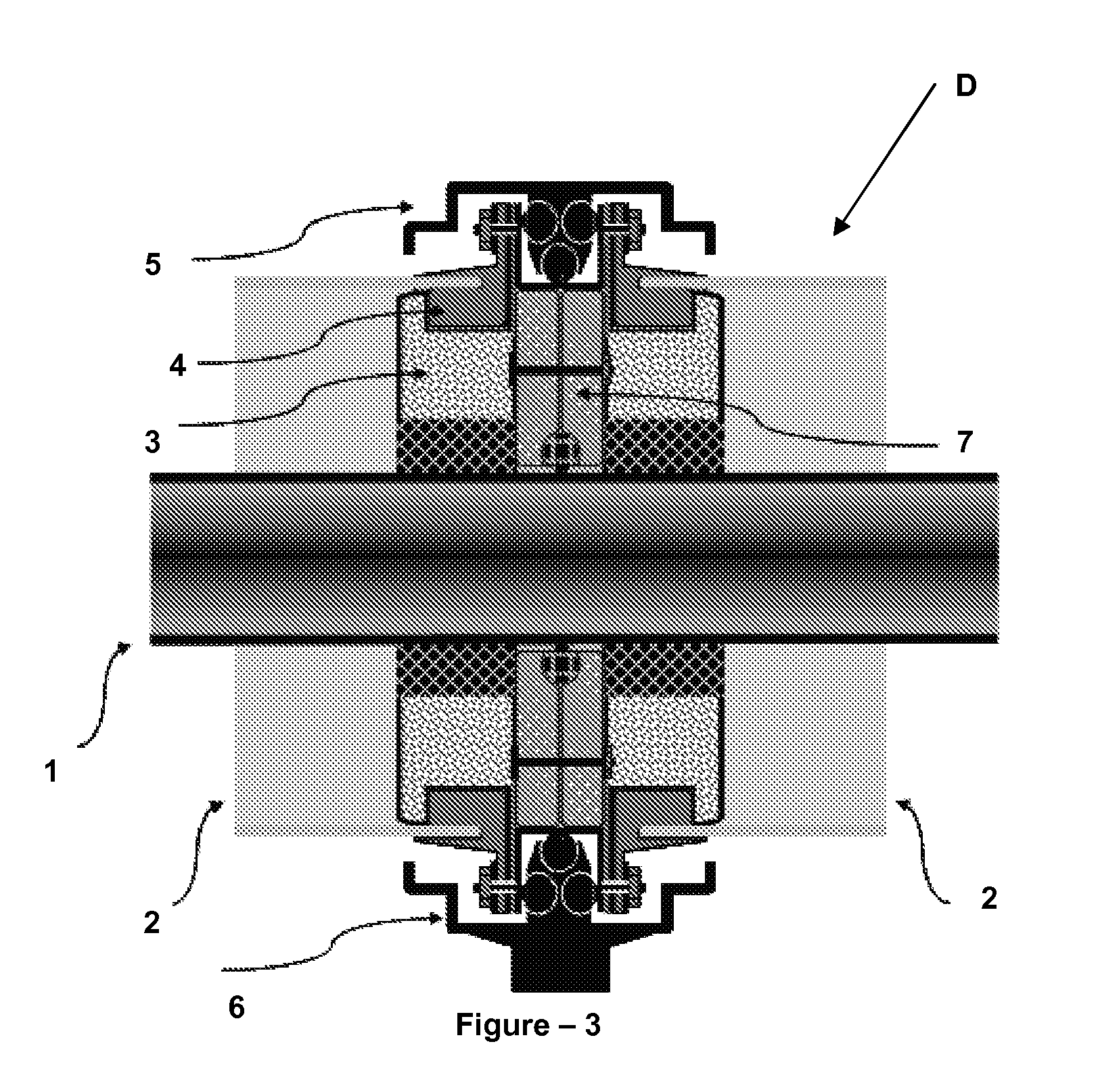
[0129]A solar trough field system according to the invention comprises multiple parabolic reflectors; a thermal receiver tube, center of which coincides with the focus of the parabolic reflectors and which consists of a metal heat receiving pipe (1) and a glass tube (2) which are nested (the glass tube surrounds the metal heat receiving pipe from outside); a “vacuum seal and glass tube connector system” (E) which connects the glass tubes (2) and the thermal heat receiving pipe (1) to each other; a rotating support unit (21), which connects the parabolic panel to the glass tube connector system (E) and provides the thermal receiver tube (1) to stay stationary while the parabolic panel is rotating around it; “flexible expansion unit” (29) located at the end of each parabolic trough unit which provides vacuum seal while the Heat Receiving Pipe (1) is moving due to heat expansion; and a vertical loop (52) located at the discharge side of the parabolic unit, which can be used instead of ...


PUM


Abstract

A solar trough field system according to the invention comprises multiple parabolic reflectors; a thermal receiver tube, center of which coincides with the focus of the parabolic reflectors and which consists of a metal heat receiving pipe (1) and a glass tube (2) which are nested (the glass tube surrounds the metal heat receiving pipe from outside); a ‘vacuum seal and glass tube connector system’ (E) which connects the glass tubes (2) and the thermal heat receiving pipe (1) to each other; a rotating support unit (21), which connects the parabolic panel to the glass tube connector system (E) and provides the thermal receiver tube (1) to stay stationary while the parabolic panel is rotating around it; ‘flexible expansion unit’ (29) located at the end of each parabolic trough unit which provides vacuum seal while the Heat Receiving Pipe (1) is moving due to heat expansion; and a vertical loop (52) located at the discharge side of the parabolic unit, which can be used instead of water separator and which also provides the heat expansion of the Heat Receiving Pipe (103).

Description

TECHNICAL FIELD[0001]This invention relates to developments on parabolic trough-shaped collectors which concentrate the sunlight on an axis of focus, converting it into other energy forms such as heat and electricity.PRIOR ART[0002]Currently, trough collectors (solar trough field system) are used to collect the sun's energy in order to obtain electricity and heat there from. These systems comprise trough-shaped long parabolic reflectors, thermal receiver tubes which are placed on the focus of the reflectors where beams coming from the reflector are collected and in which a fluid exists, and a rotating mechanism which aligns the reflectors to the sun. The beams coming to the reflectors which are directed towards the sun are reflected and collected on the thermal receiver tube which is located on the focus of the reflector. Thermal receiver tube is provided with two nested tubes where a vacuum setting is located in the space there between. A fluid, which provides the heat transfer, is...

Claims


Application Information

Patent Timeline
IPC IPC(8): F24J2/12F24J2/50F24J2/38F24J2/52F24S10/40F24S23/71F24S23/74F24S50/20
CPCF24J2/055Y02E10/47F24J2/14F24J2/4612F24J2/4616F24J2/4636F24J2/4638F24J2/4647F24J2/541F24J2002/4681F24J2002/5275Y02E10/41Y02E10/44Y02E10/45F24J2/07F24S40/85F24S2025/6013F24S40/80F24S80/30F24S23/74F24S20/20F24S30/425F24S40/46F24S2025/011F24S40/40F24S10/45Y02E10/40
Inventor CAPAN, RAHMI OGUZ
Owner HSE HITIT SOLAR ENERJI ANONIM SIRKETI
Why Eureka
Try Eureka