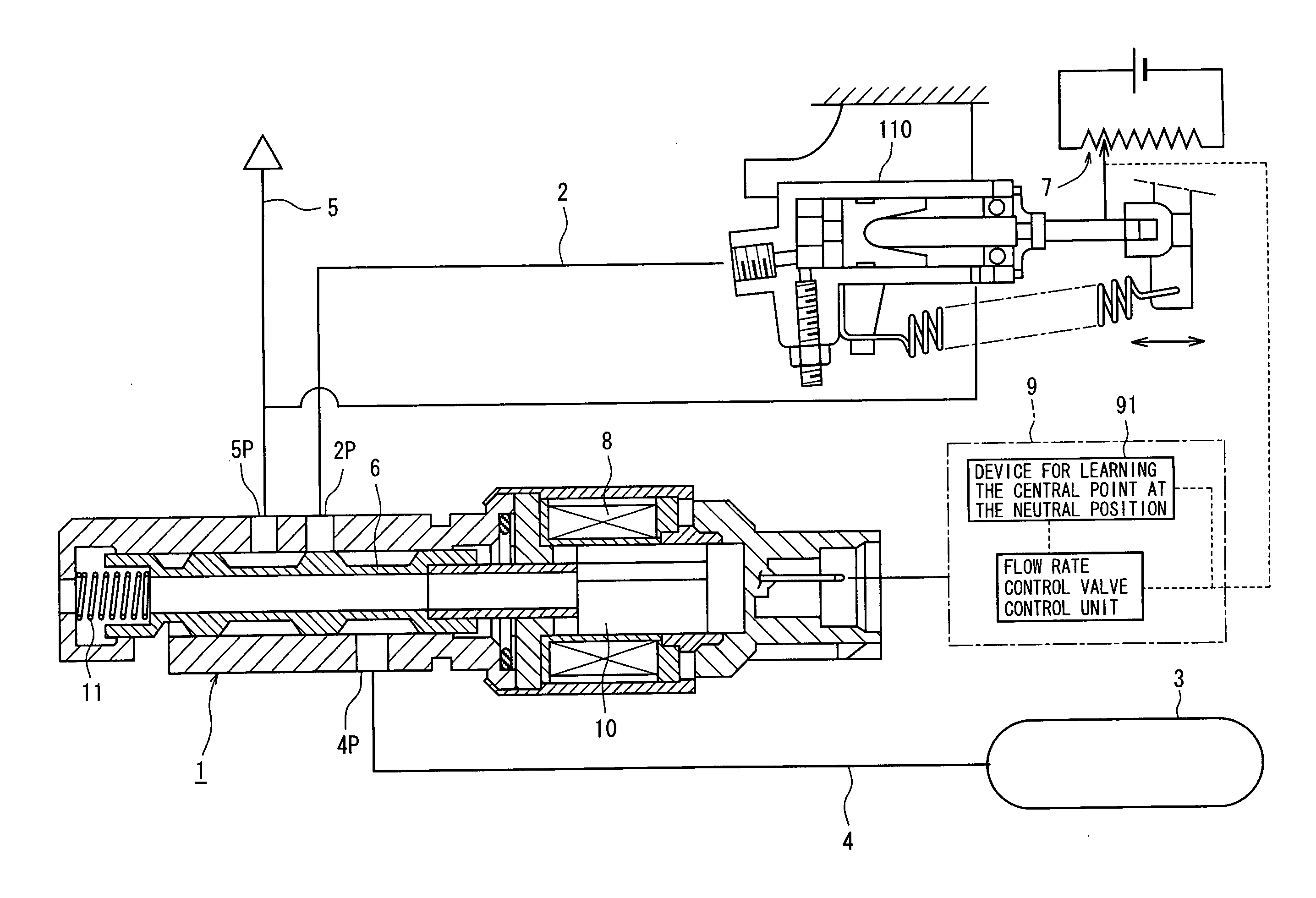
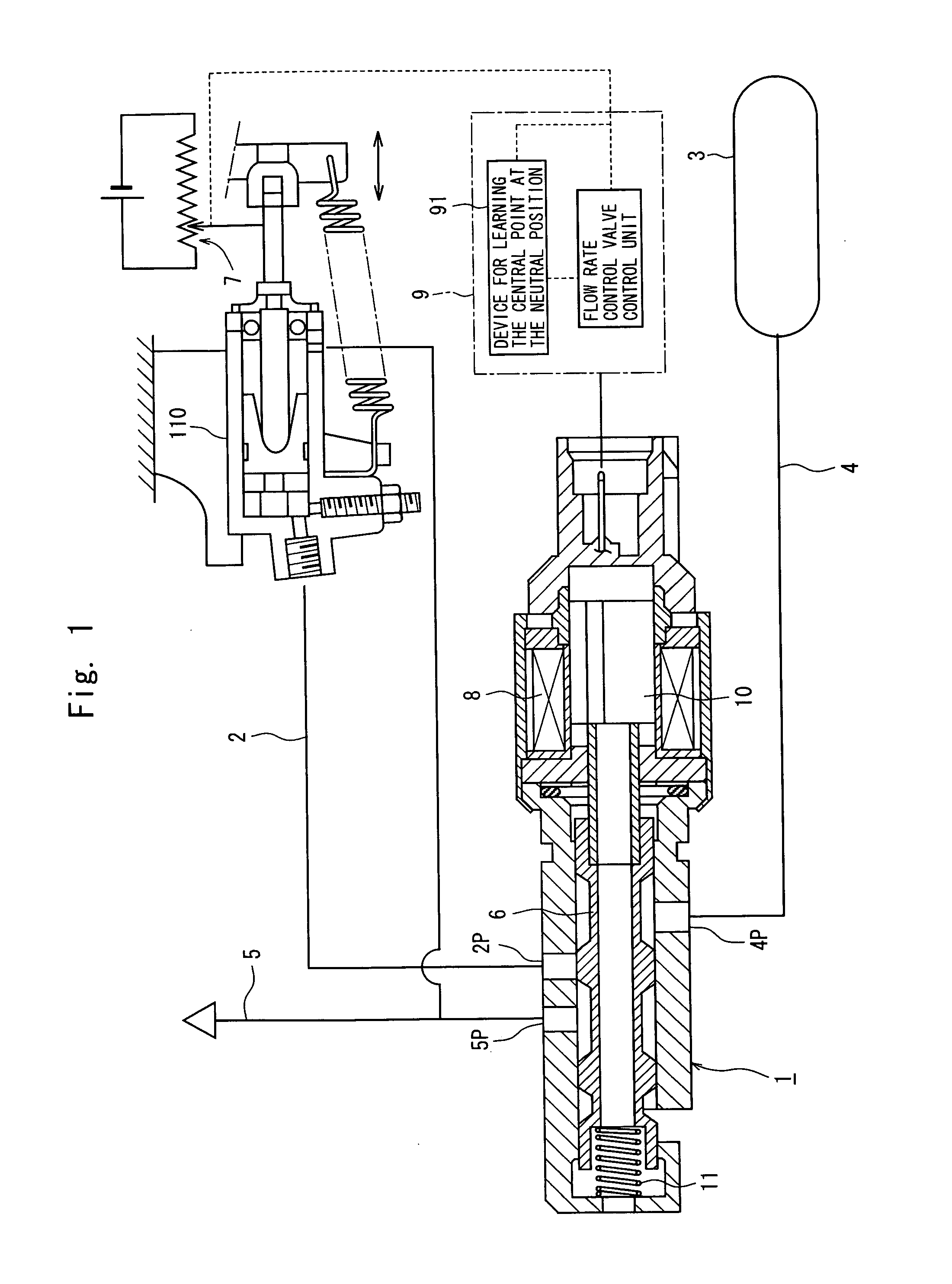
[0026]When the single flow rate control valve is provided in the
clutch control device and the working fluid is fed into, or discharged from, the clutch actuator through the flow rate control valve, the valve body in the flow rate control valve is displaced to one side from the
neutral position to feed the working fluid, and is displaced to the other side to
discharge the working fluid. The flow rate control valve control device of the present invention is provided with the learning device for learning the neutral position, and learns, at all times, the operation amount of the
valve actuator that becomes the central point at the neutral position of the flow rate control valve in which the neutral position has a width and includes an dead zone (e.g., leans the amount of
electric current flowing into the coil of the electromagnetic solenoid). Even if the central point changes at the neutral position due to a difference inherent in the individual flow rate
control valves or due to secular change, the amount of operating the
valve actuator is adjusted relying upon the central point stored in the learning device, and the position of the valve body in the flow rate control valve is correctly controlled as to attain a target flow rate. It is, therefore, made possible to quickly and correctly change the rate of connection of the clutch at the time of gear shifting and to attain a clutch control without shift shock. In the case of a flow rate control valve without dead zone at the neutral position, the central point at the neutral position becomes the neutral position itself. It is, therefore, obvious that upon learning the neutral position, the amount of operating the
valve actuator can similarly be adjusted even in the flow rate control valve without dead zone.
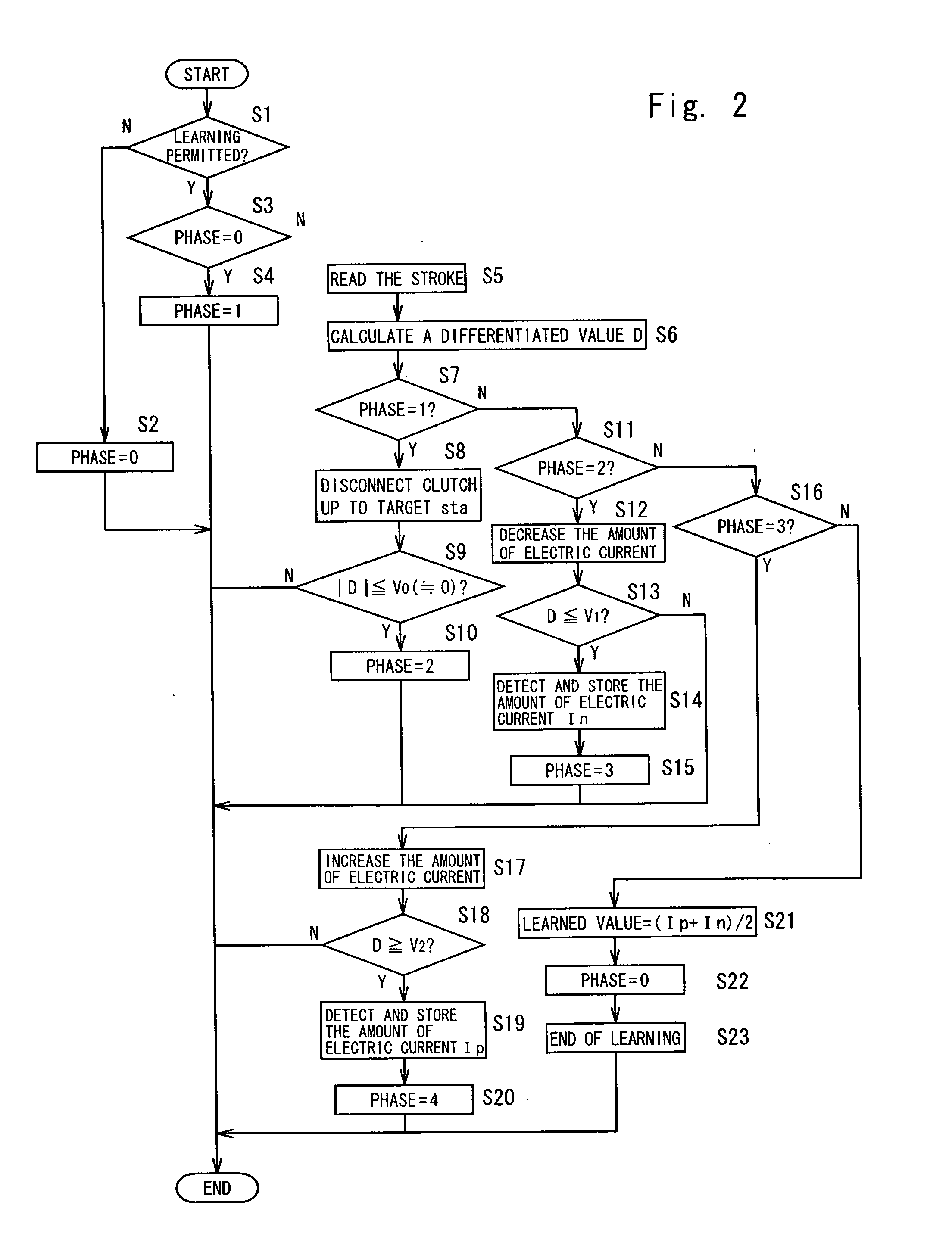
[0027]Further, the neutral position learning device of the present invention executes the operation for increasing the movement of the clutch actuator after the movement thereof is decreased, detects a first operation amount which is the operation amount of the valve actuator at a moment when a rate of change in the detection
signal of the stroke sensor has reached a predetermined value while the detection
signal of the stroke sensor is decreasing, and detects a second operation amount which is the operation amount of the valve actuator at a moment when the rate of change in the detection
signal of the stroke sensor has reached a rate of change of which the absolute value is equal to the above predetermined value while it is increasing. In other words, the learning device detects the first operation amount at a moment when the rate has reached a predetermined value (−) while the movement of the clutch actuator is decreasing and the second operation amount at a moment when the rate has reached a predetermined value (+) of the same absolute value while the movement thereof is increasing. A value obtained by averaging the first operation amount and the second operation amount is decided to be the central point at the neutral position. This makes it possible to detect the central point at the neutral position on account of the reasons described below.
[0028]As shown in FIG. 11, the flow rate characteristics representing a relationship between the operation amount of the flow rate control valve (amount of
electric current) and the flow rate are symmetrical on the feed side and on the
discharge side with the neutral position or the central point as a point of symmetry. The characteristics of
point symmetry remain the same as shown in FIG. 12 despite the central point at the neutral position changes due to secular change. The rate of change in the stroke of the clutch actuator varies in proportion to the flow rate of the flow rate control valve. If the flow rate on the feed side is equal to the flow rate on the discharge side, therefore, the rates of change in the stroke are opposite but have the same absolute value. Therefore, the neutral position learning device of the present invention finds an operation amount at the central point at the neutral position by deciding the central point at the neutral position by averaging the operation amount of the valve actuator at a moment when a predetermined value is reached while the stroke is decreasing, e.g., averaging the amount of electric current In that corresponds to the flow rate −Q0 in FIG. 11 and the operation amount of the valve actuator at a moment when the rate of change is reached of which the absolute value is equal to that of the above predetermined value while the stroke is increasing, e.g., the amount of electric current Ip that corresponds to the flow rate +Q0 in FIG. 11.
[0029]The stroke sensor used in the learning device of the present invention is a part that has primarily been provided for the clutch control device for controlling the rate of connection of the clutch. Therefore, the learning device of the present invention is capable of learning the central point at the neutral position without the need of providing any particular part. Further, the learning is executed while the stroke of the clutch actuator is changing without affected by
static friction, and there is no decrease in the accuracy of learning. Besides, since the clutch control device uses only one flow rate control valve, the control device as a whole can be simply constituted in a compact size.
[0030]In the invention of claim 2, the neutral position learning device works to increase the movement of the clutch actuator up to a position where the clutch is completely disconnected, i.e., executes the learning by increasing the stroke to near its maximum value prior to executing the operation for increasing the movement of the clutch actuator after the movement thereof is decreased. That is, the learning device of the present invention learns the central point at the neutral position by increasing and decreasing the stroke of the clutch actuator, and is capable of executing the learning even when the stroke is at an intermediate position at the time of learning. Here, if the stroke is increased to near its maximum value prior to executing the learning, the clutch actuator once moves over its full stroke. Therefore, the learning is executed in a region where the clutch actuator stably operates, and the accuracy of learning is improved.
[0031]In the invention of claim 3, the neutral position is learned with the transmission being rendered to be neutral when the vehicle is at a halt and the
brake of the vehicle is being applied. Upon executing the neutral position learning of the present invention, the rate of connection of the clutch varies accompanying an increase or a decrease in the stroke of the clutch actuator. It is, therefore, desired to execute the learning with the transmission being rendered to be neutral while the vehicle is at a halt so will not to affect the power
transmission system of the vehicle. Upon executing the learning while the
brake of the vehicle is being applied, the occurrence of unexpected start of the vehicle is prevented even in case erroneous operation happens to occur, and the neutral position can be learned maintaining safety.
