
Vacuum-Assisted Resin Transfer Molding Process with Reusable Resin Distribution Line

a technology of reusable resin and transfer molding process, which is applied in the direction of dough shaping, manufacturing tools, applications, etc., can solve the problems of fiber preform compression pressure, and achieve the effect of facilitating resin delivery

Active Publication Date: 2011-07-14
LOCKHEED MARTIN CORP
View PDF16 Cites 31 Cited by
  • Summary
  • Abstract
  • Description
  • Claims
  • Application Information

AI Technical Summary

Benefits of technology

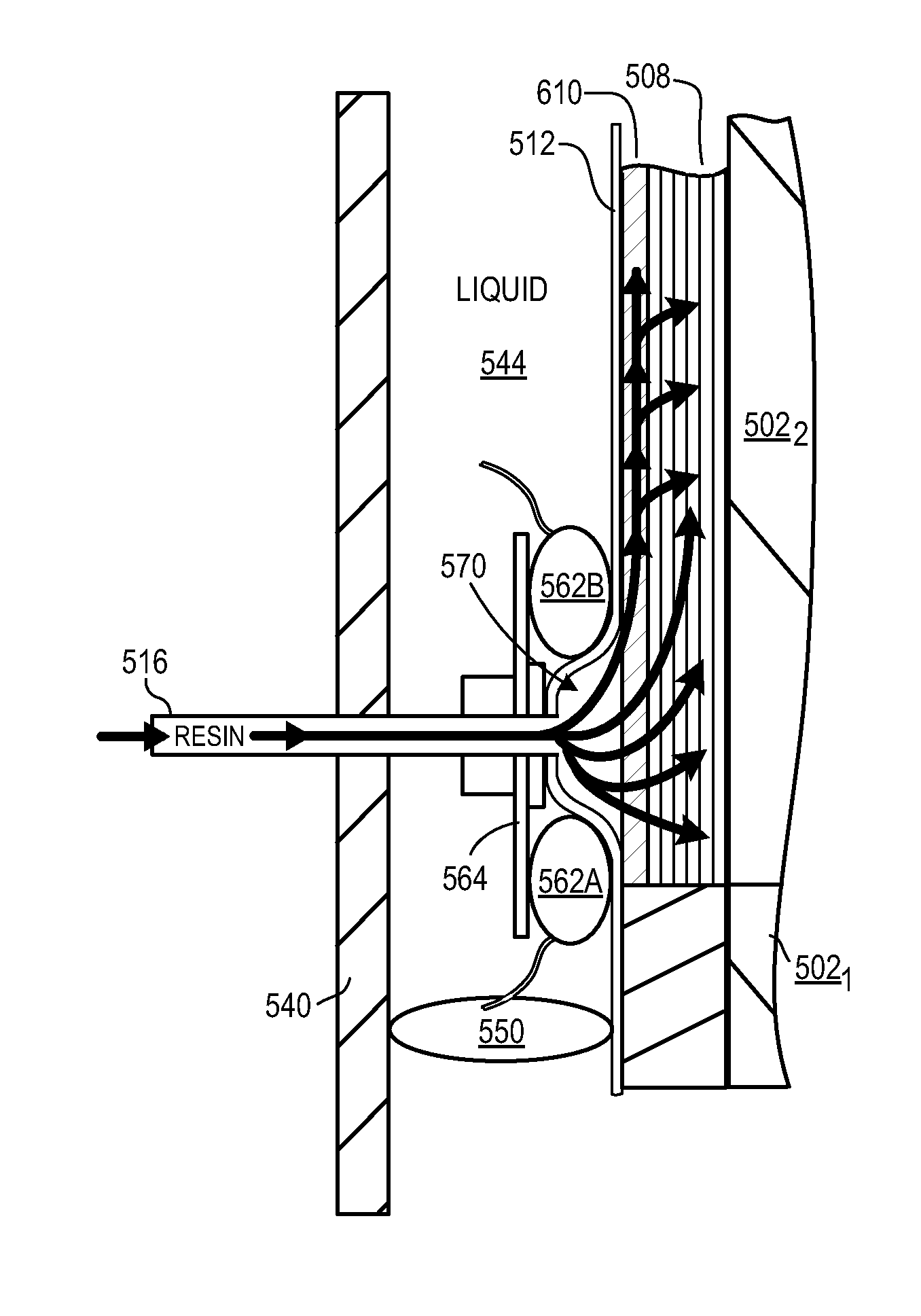
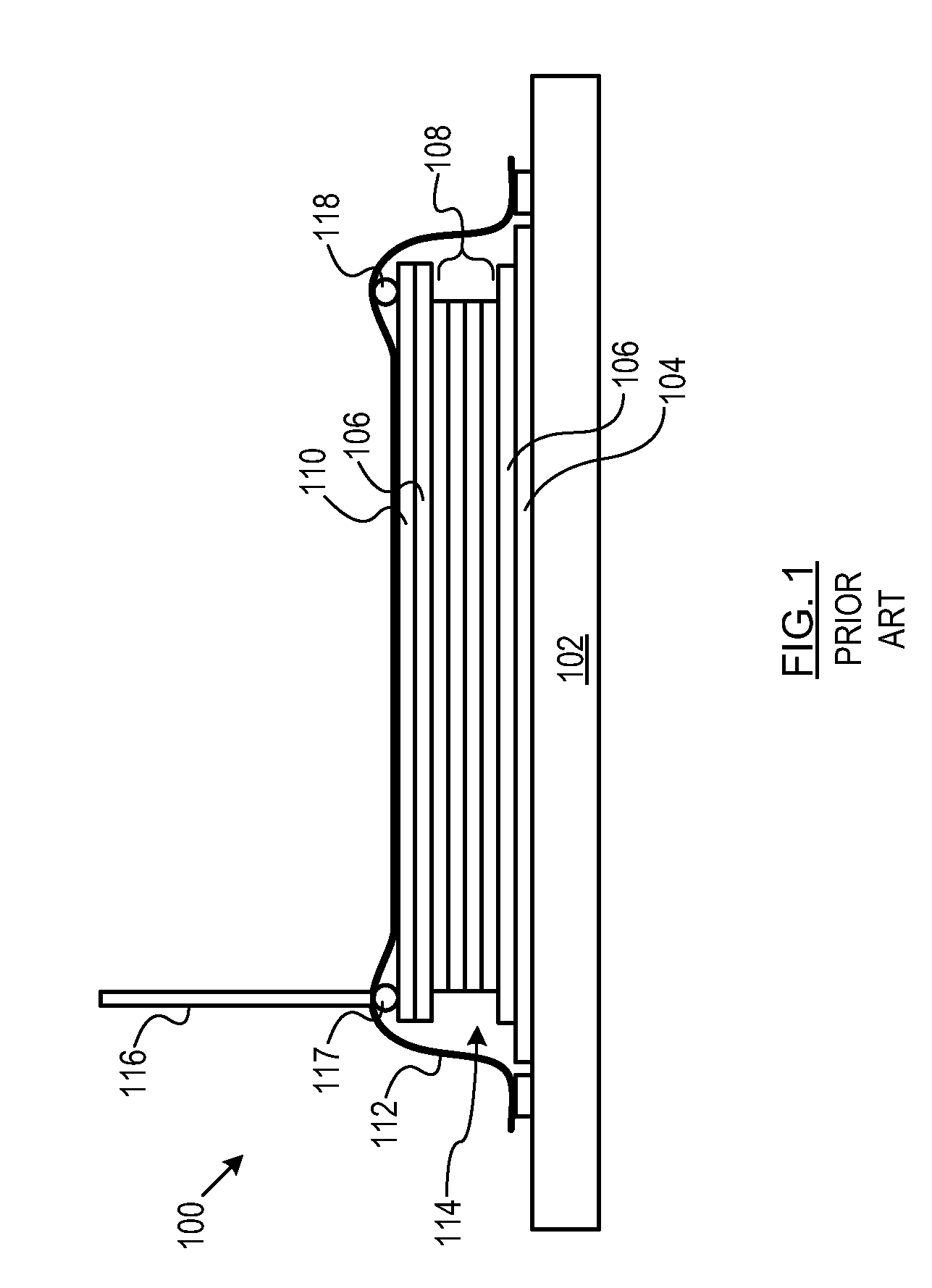
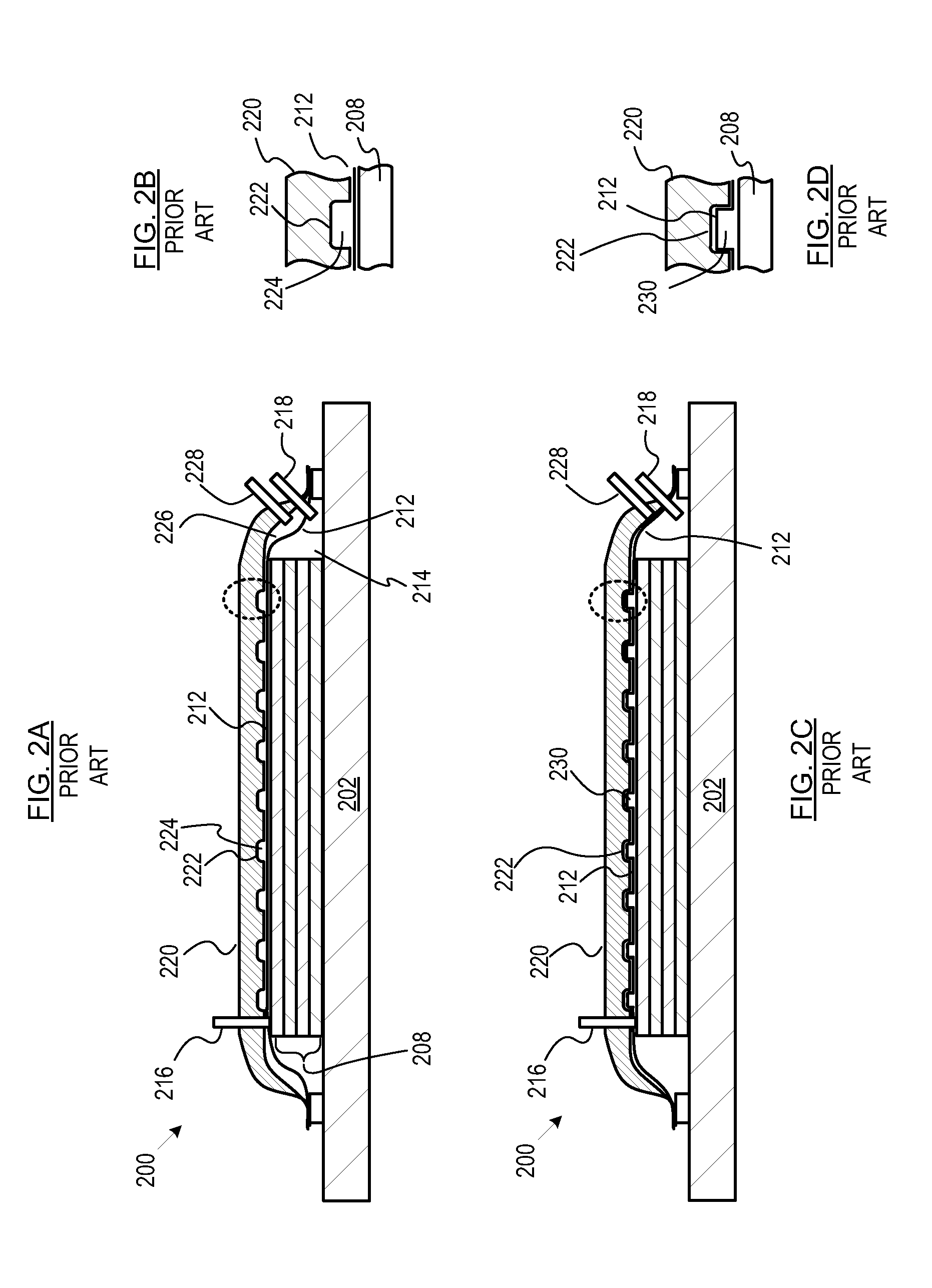
[0025]In operation, a vacuum is established in the region between the soft tool and the hard tool. This draws the soft tool against the resin distribution medium / fiber preform that is disposed in that region. The second side of the soft tool is exposed to at least atmospheric pressure. This pressure differential—atmospheric or greater pressure on the second side of the soft tool and vacuum on the first side of the soft tool results in a compaction pressure that acts on the fiber preform. To facilitate delivery of the resin to the fiber preform, a passage—the reusable resin distribution line—is formed between the soft tool and the resin distribution medium / fiber preform.
[0026]To form the RRDL, the inflatable bladders of the RRDL forming arrangement are inflated. Since the bridge overlies the bladders, it moves away from the resin distribution medium / fiber preform as the bladders inflate. Since the soft tool is coupled to the bridge, it is pulled away from the resin distribution media / fiber perform with the bridge in the region between the two bladders. A passage—the RRDL—results. Resin is delivered from the resin inlet line to the RRDL. Once inside the RRDL, the resin readily travels down the length of the RRDL, permeates the resin distribution medium, and then infuses throughout the fiber preform.

Problems solved by technology

This pressure differential—atmospheric or greater pressure on the second side of the soft tool and vacuum on the first side of the soft tool results in a compaction pressure that acts on the fiber preform.

Method used


Image

  • Vacuum-Assisted Resin Transfer Molding Process with Reusable Resin Distribution Line
  • Vacuum-Assisted Resin Transfer Molding Process with Reusable Resin Distribution Line
  • Vacuum-Assisted Resin Transfer Molding Process with Reusable Resin Distribution Line

Examples


Embodiment Construction

[0059]Definitions. The terms appearing below are provided with the follow explicit definitions for use in this description and the appended claims.[0060]“Shot” refers to the amount of resin that is required to fill a molding region or mold cavity. A “multi-shot” article requires multiple, sequential resin fills and cures within the mold cavity.[0061]“Workpiece” means the structure that is produced or the assemblage (e.g., core, fiber, resin) that will form that structure in a single shot in the molding region. In the context of multi-shot articles, the workpiece therefore represents a portion or segment of the final composite article (e.g., a segment of the cold water pipe, etc).[0062]“Reinforcement constituent” of a composite material provides certain characteristic properties (usually strength and / or stiffness elated, but also density, electrical resistivity, thermal conductivity, etc.) to the composite. The reinforcement constituent is typically fiber based, such as to produce a ...


PUM

PropertyMeasurementUnit
Pressureaaaaaaaaaa

Abstract

A method and apparatus for a reusable resin distribution line for use in conjunction with a resin transfer molding apparatus is disclosed. The apparatus includes a soft tool and a hard tool (i.e., mold). In the illustrative embodiment, two inflatable bladders are disposed on a side of the soft tool, wherein a bridge spans the bladders. The soft tool is coupled to the bridge. When the bladders are inflated, the bridge moves away from the hard tool, drawing the soft tool away from the hard tool in the region between the bladders. This creates a temporary passage or reusable resin distribution line for distributing resin to a reinforcement constituent disposed between the soft tool and the hard tool.

Description

STATEMENT OF RELATED CASES[0001]This case is a continuation-in-part of U.S. patent application Ser. No. 12 / 484,779 filed Jun. 15, 2009, which is incorporated herein.FIELD OF THE INVENTION[0002]The present invention relates to the production of composite materials and structures.BACKGROUND OF THE INVENTION[0003]Fiber-reinforced polymer-matrix composite materials are used for a variety of structural applications. These composite materials, which include a matrix constituent, typically a resin, and a reinforcement constituent, typically a fiber bundle or woven fabric, are formed via a molding operation.[0004]One method for forming composite materials is a process called “resin transfer molding” or “RTM.” In this process, resin is added under pressure into a closed-cavity mold. In the simplest version of RTM, air is left in the fibers before resin injection. Some but not all of this air is driven out through vents as the fibers fill with resin. In order to obtain an acceptable void cont...

Claims


Application Information

Patent Timeline
IPC IPC(8): B29C45/14
CPCB29C70/443B29L2023/22B29D23/001B29C70/548
Inventor MILLER, ALAN K.ROSARIO, JR., THEODORE
Owner LOCKHEED MARTIN CORP
Learn More