Modular power supply arrangement, in particular for reactors for producing polysilicon

Inactive Publication Date: 2011-07-14
AEG POWER SOLUTIONS BV
View PDF8 Cites 12 Cited by
  • Summary
  • Abstract
  • Description
  • Claims
  • Application Information

AI Technical Summary

Benefits of technology

[0007]It is an object of the invention to improve a power supply arrangement of the aforedescribed type such that starting with a simple power supply arrangeme

Problems solved by technology

Another disadvantage of this type of power supply arrangement as well as of ot

Method used


Image

  • Modular power supply arrangement, in particular for reactors for producing polysilicon
  • Modular power supply arrangement, in particular for reactors for producing polysilicon
  • Modular power supply arrangement, in particular for reactors for producing polysilicon

Examples


Embodiment Construction

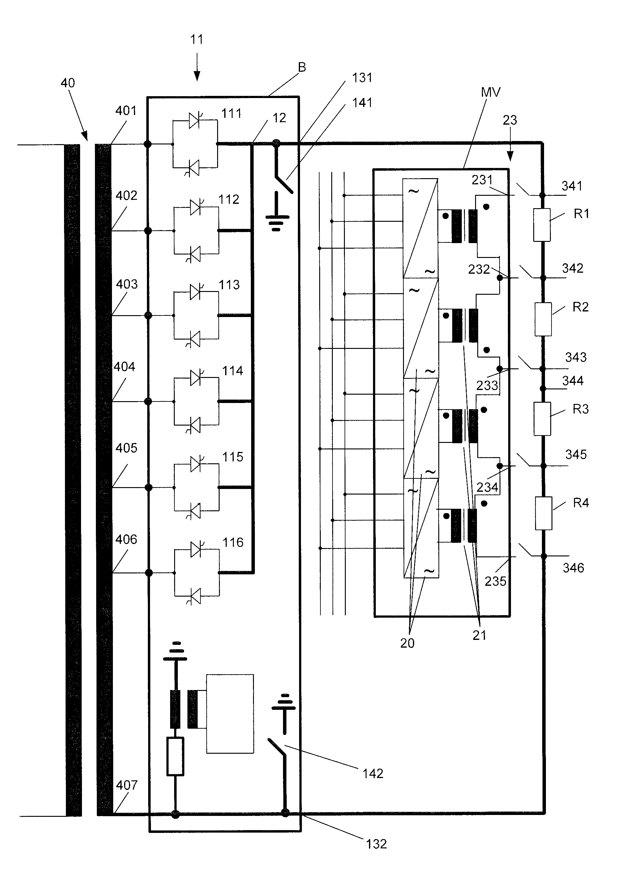
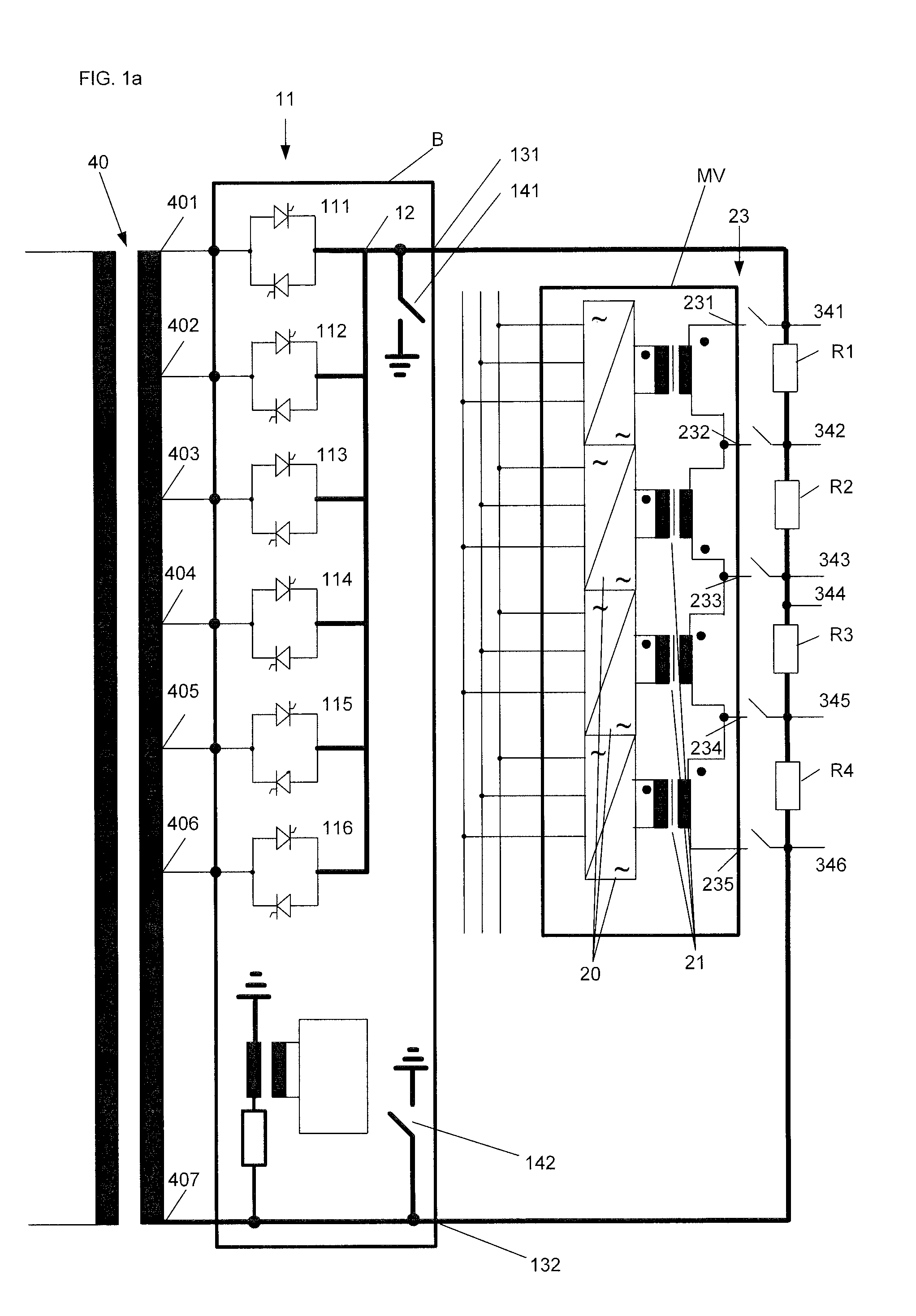
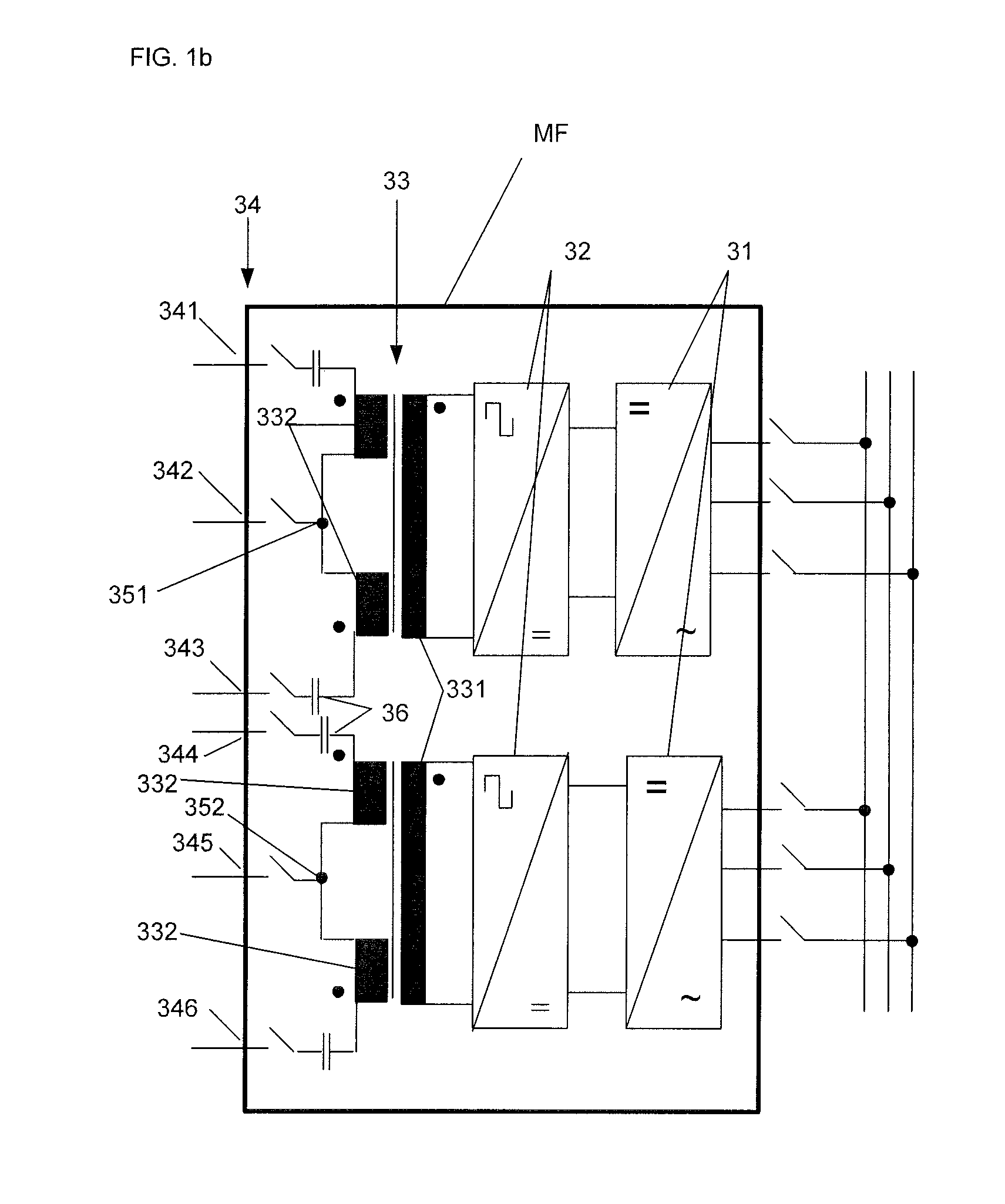
[0035]FIG. 1 shows the wiring connections of the modular power supply arrangement according to the invention, as well as a transformer 40, a basic supply module B, a medium voltage supply module MV and a medium frequency supply module MF. A control module and a communication bus are not illustrated. Also not illustrated are the control lines, the measured value recorder and the measured value lines located inside the basic supply module B, the medium voltage supply module MV and the medium frequency supply module MF, and the interfaces and interface driver circuits of the modules B, MV MF to the communication bus. Likewise, optional control units and / or driver or trigger circuits optionally arranged downstream of the control module and disposed in the basic supply module B, the medium voltage supply module MV and the medium frequency supply module MF are also not shown.

[0036]The basic supply module B of the modular power supply arrangement according to FIG. 1 includes a mains connec...


PUM


Abstract

A power supply arrangement for producing polysilicon with a central control unit and a basic supply unit, which are regulated and controlled by control means. The basic supply unit supplies the supply module with electric energy, an output for connecting to loads which are supplied with electric energy from the mains via basic supply unit, and controllable switches, which are connected to the input and to the output and which are configured for adjusting the energy to be supplied to the loads. The switches are controllable. The control unit is supplied with electric energy. The power supply includes a communication bus. The control module and the basic supply module are connectable to the control module and the basic supply module to the communication bus. The control module and the basic supply module provide connections to the control module and the basic supply module to the communication bus.

Description

BACKGROUND OF THE INVENTION[0001](1) Field of the Invention[0002]The present invention relates to a power supply arrangement, in particular for reactors for producing polysilicon, with a control unit and at least one basic supply unit, wherein the control unit comprises at least one control and regulating means for controlling and / or regulating the basic supply unit, the basic supply unit comprises, at least one input for connection to a power mains for supplying electric energy, at least one output for connecting with a group of loads which can be supplied via the basic supply unit with electric energy from the power mains, and controllable switches, preferably thyristors, which are connected at least indirectly with the input and at least indirectly with the output and which are configured for adjusting the energy to be supplied to the loads via the output, wherein the switches can be controlled by the control unit.[0003](2) Description of Related Art[0004]A power supply arrangeme...

Claims


Application Information

Patent Timeline
IPC IPC(8): H02J3/00
CPCH02J3/38H02M5/22H02M1/0067
Inventor WALLMEIER, PETER
Owner AEG POWER SOLUTIONS BV
Why Eureka
Try Eureka