Energy harvesting device using pyroelectric material

Inactive Publication Date: 2011-07-14
SAMSUNG ELECTRONICS CO LTD
View PDF29 Cites 19 Cited by
  • Summary
  • Abstract
  • Description
  • Claims
  • Application Information

AI Technical Summary

Benefits of technology

[0010]According to an aspect of a described embodiment, there is provided an energy harvesting device which includes a first heat source; a second heat source having a temperature higher than that of the first heat source; and a cantilever which is interposed between the first heat source and the second heat source and has a stacked structure including a first film formed of a pyroelectric mat

Problems solved by technology

However, methods utilizing thermoelec

Method used


Image

  • Energy harvesting device using pyroelectric material
  • Energy harvesting device using pyroelectric material
  • Energy harvesting device using pyroelectric material

Examples


Embodiment Construction

[0028]Reference will now be made in detail to embodiments, examples of which are illustrated in the accompanying drawings, wherein like reference numerals refer to the like elements throughout. In this regard, the present embodiments may have different forms and should not be construed as being limited to the descriptions set forth herein. Accordingly, the embodiments are merely described below, by referring to the figures, to explain aspects of the present description.

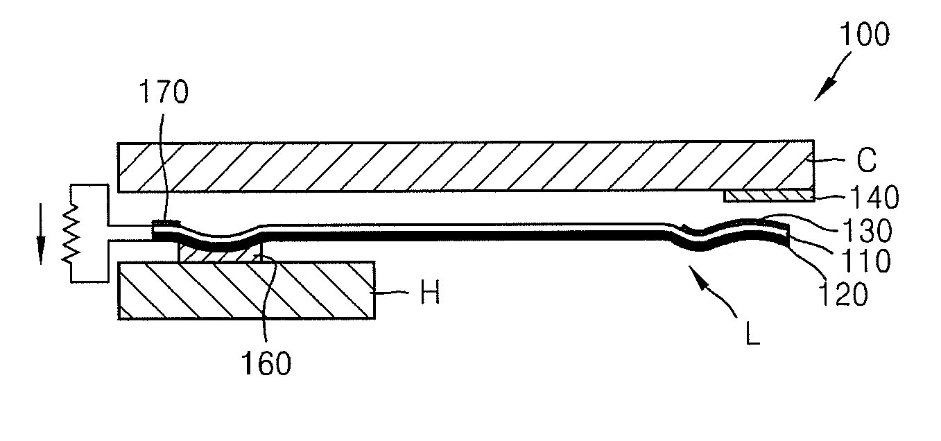
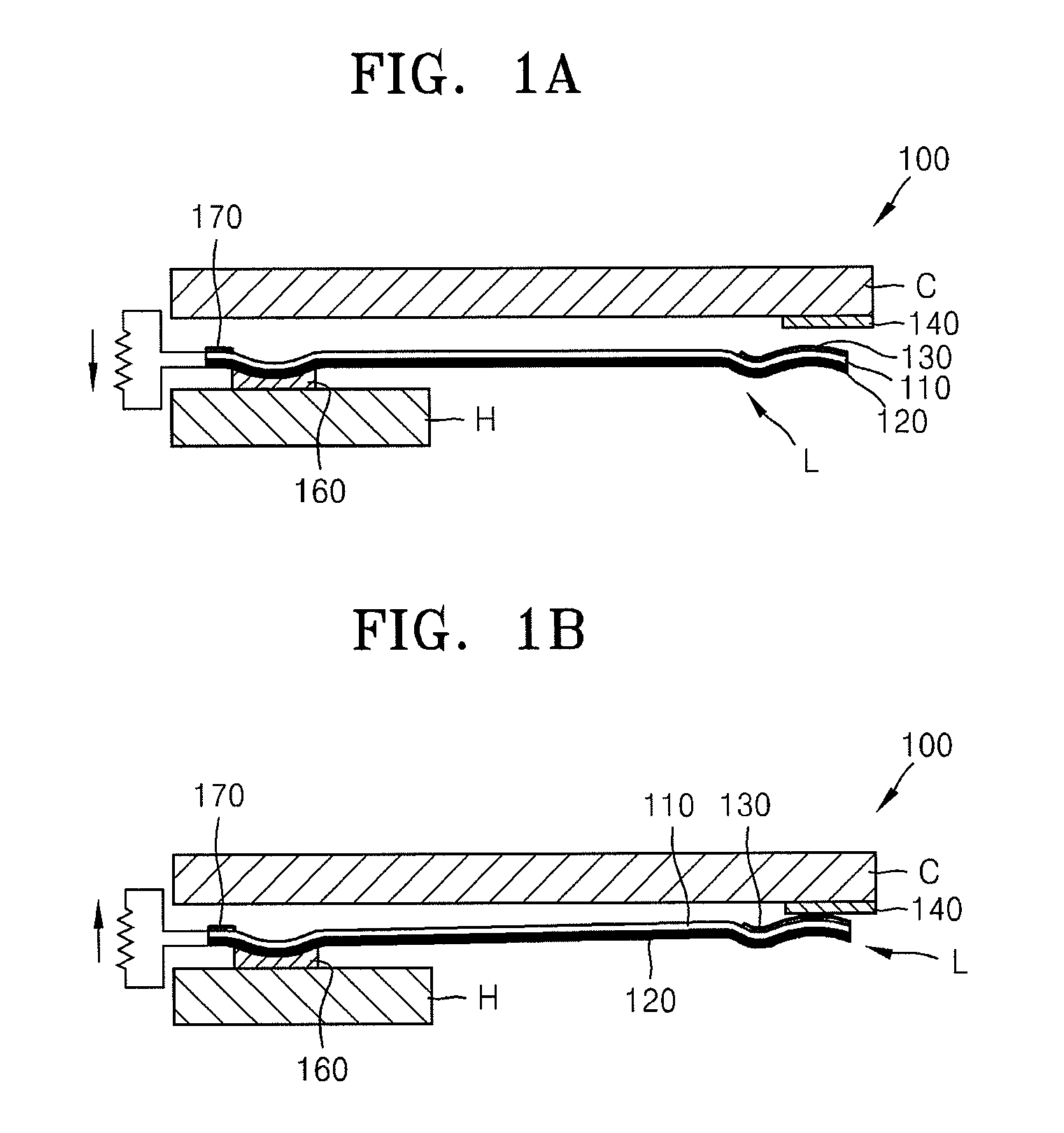
[0029]Energy harvesting devices according to embodiments described herein generate electric energy by using pyroelectric materials. Hereinafter, the mechanism of generating electric energy by using a pyroelectric material will be briefly described. When a pyroelectric material is heated or cooled, the locations of atoms within the crystal structures of the pyroelectric material are changed, and thus, the size of an electric dipole is changed. As a result, a potential difference occurs within the pyroelectric material,...


PUM


Abstract

Provided is an energy harvesting device using pyroelectric materials. The energy harvesting device includes a first heat source; a second heat source having a temperature higher than a temperature of the first heat source; and a cantilever which is interposed between the first heat source and the second heat source, the cantilever including a first film formed of a pyroelectric material and a second film, where the first film is disposed on the second film and a thermal expansion coefficient of the second film is different from that of the pyroelectric material of the first film. Electric energy is generated by periodically changing a temperature within the first film.

Description

CROSS-REFERENCE TO RELATED APPLICATIONS[0001]This application claims priority from Korean Patent Application No. 10-2010-0002383, filed on Jan. 11, 2010, in the Korean Intellectual Property Office, the disclosure of which is incorporated herein in its entirety by reference.BACKGROUND[0002]1. Field[0003]Apparatuses and methods consistent with the present disclosure relate to energy harvesting devices.[0004]2. Description of the Related Art[0005]Energy harvesting technologies are technologies for converting energy, such as vibrations, heat, light, radio frequency (RF), or the like, from the surrounding environment into electric energy by using a converting device. The efficiency of harvesting electric energy has continuously increased along with the developments of the structures and performances of energy harvesting devices. Furthermore, as the voltages and currents for driving semiconductor devices have decreased, electronic devices capable of performing various functions with reduc...

Claims


Application Information

Patent Timeline
IPC IPC(8): H02N10/00
CPCH02N10/00H01L37/02H10N15/10H02N11/002Y10S257/93B60H2001/2275
Inventor LIM, JI-HYUK
Owner SAMSUNG ELECTRONICS CO LTD
Why Eureka
Try Eureka