This helps you quickly interpret patents by identifying the three key elements:
Problems solved by technology
Method used
Benefits of technology
Benefits of technology
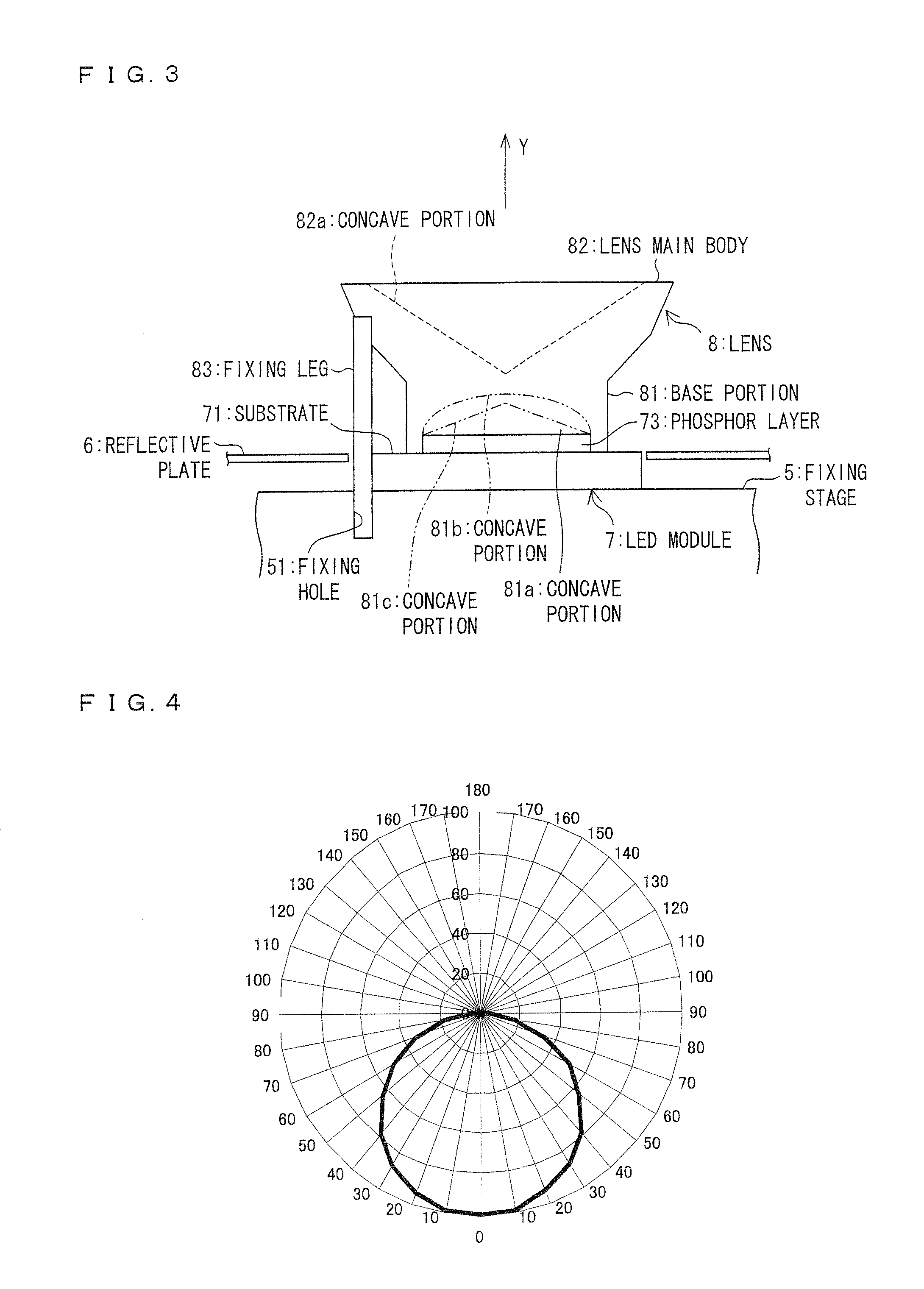
[0015]As described above, the LED light bulb according to the present invention includes a lens which directs part of outgoing light to (i) first directions perpendicular to a front emission direction of the outgoing light or (ii) second directions leaning to the cap beyond the first directions. Therefore, by setting reflection directions of the lens properly, the light distribution can be easily adjusted, and blocking the outgoing light by the housing and the like can be reduced, thereby raising the light output ratio.
Problems solved by technology
However, this light bulb has disadvantages as follows: (i) The LEDs are externally visible, thereby making the light bulb less attractive aesthetically.
(ii) A complex configuration of a substrate increases a cost.
However, in terms of heat dissipation and the like, this kind of LED cannot be realized by a high-power LED.
However, this results in a decrease in conversion efficiency from electric energy to light in a case where a number of high-power LEDs are used.
Method used
Image
Click on the blue label to locate the original text in one second.
Reading with bidirectional positioning of images and text.
Examples
embodiment 1
[0040]The following describes an embodiment of the present invention with reference to FIGS. 1 to 4.
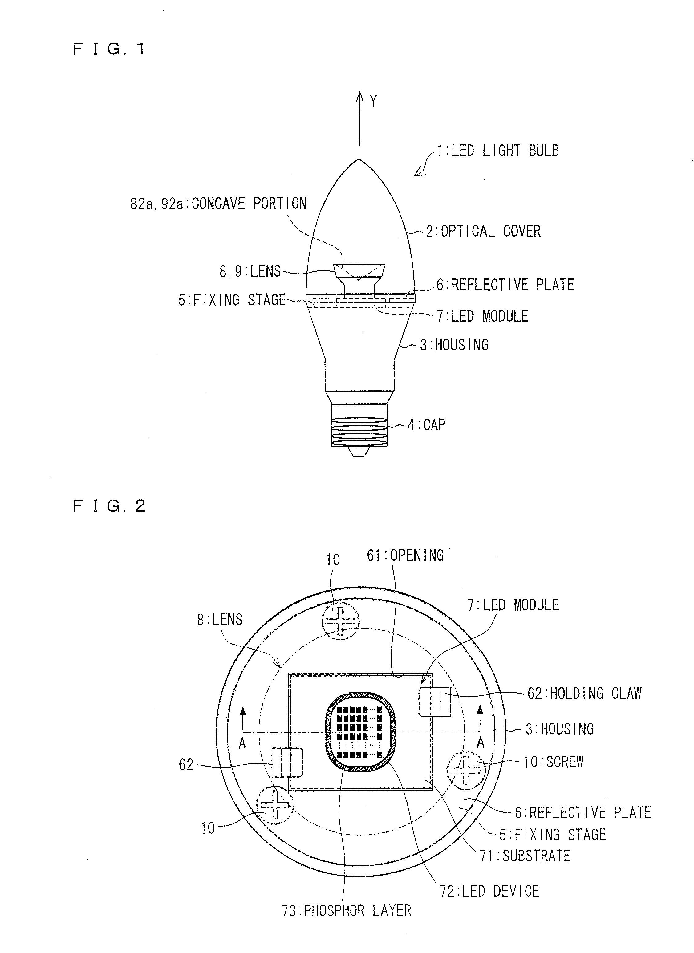
[0041]FIG. 1 illustrates an LED light bulb 1 according to the present embodiment. FIG. 2 is an enlarged view illustrating where an LED module 7 and a lens 8 are located in the LED light bulb 1. FIG. 3 is a cross-sectional view taken along line
[0042]A-A in FIG. 2, illustrating a structure of the lens 8 in the LED light bulb 1.
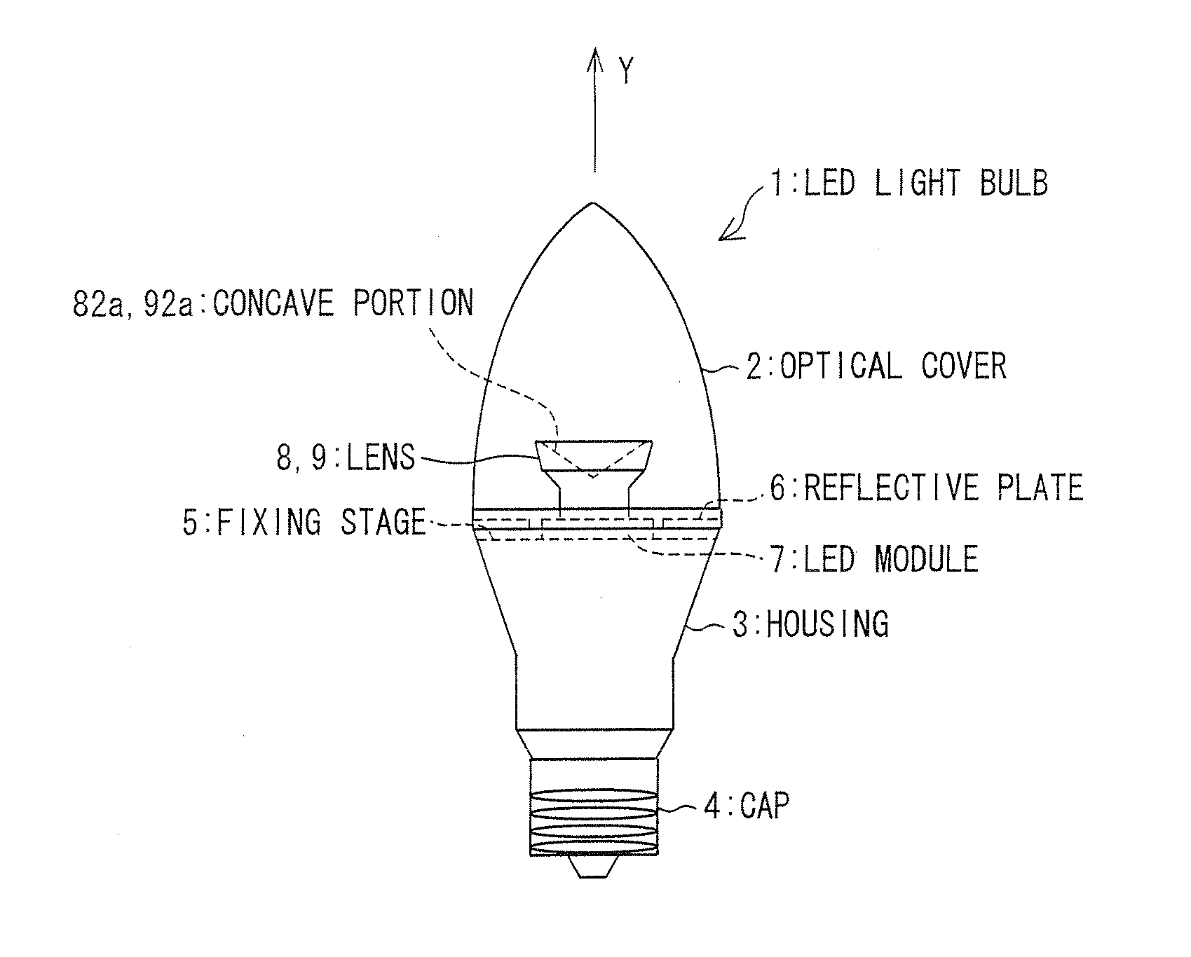
[0044]As illustrated in FIGS. 1 and 2, the LED light bulb 1 includes an optical cover 2, a housing 3, a cap 4, a fixing stage 5, a reflective plate 6, and the LED module 7.
[0045]The optical cover 2, thorough which the light emitted from the LED module 7 passes, covers the LED module 7 for protection. The optical cover 2 is made of a transparent resin or glass. It is particularly preferable that the optical cover 2 be made of a light-diffusive resin having a haze value of 99%. A surface of the optical cover 2 may be processed ...
embodiment 2
[0078]The following describes another embodiment of the present invention with reference to FIGS. 9 and 10. FIG. 9 is a side view illustrating a light bulb 11 according to the present embodiment. FIG. 10 is an enlarged view illustrating where an LED module 7 and a lens 9 are located in the LED light bulb 11.
[0079]Note that, in the present embodiment, members having the same functions as those in Embodiment 1 are denoted by the same reference signs and are not explained.
[0081]As depicted in FIG. 9, the LED light bulb 11 of the present embodiment includes the lens 9 of the foregoing modification of the LED light bulb 1. Further, the light bulb 11 includes a fixing stage 12 instead of the fixing stage 5 of the LED light bulb 1.
[0082]The fixing stage 12 is formed to have a shape of a circular truncated cone that projects away from the cap 4, beyond the end of the housing 3 to which the optical cover 2 is attached (i.e., the fixing stage 12 is forme...
PUM
Abstract
In an LED light bulb, an LED module and a lens are disposed on a fixing stage provided to a housing. The lens has a concave portion at its top end. The concave portion forms a reflecting surface which reflects part of outgoing light from the LED module to (i) first directions perpendicular to a front emission direction of the outgoing light or (ii) second directions leaning to a cap beyond the first directions. Due to diffusion effect of an optical cover, part of the light reflected by the lens is emitted backward (toward the cap). This realizes an LED light bulb that distributes light over an entire circumference and has high output as well as high light output ratio.
Description
[0001]This Nonprovisional application claims priority under 35U.S.C. §119(a) on Patent Application No. 2010-003409 filed in Japan on Jan. 8, 2010, the entire contents of which are hereby incorporated by reference.TECHNICAL FIELD[0002]The present invention relates to an LED light bulb which has high light output ratio and can emit light over a wide angular range.BACKGROUND ART[0003]A recent increase of environmental awareness has been stimulating a replacement of a power-consuming illumination light source such as an incandescent light bulb with a power-saving light source. For example, as disclosed in Patent Literature 1, LEDs are coming into use in many cases instead of incandescent light bulbs. An LED has high luminous efficiency. Moreover, unlike fluorescent lamps, it is mercury-free. Therefore, the LED is highly expected as an environment-friendly light source. The LED is a point light source and has high directivity. As such, it has a feature of emitting intense light forward, ...
Claims
Application Information
Patent Timeline
Application Date:The date an application was filed.
Publication Date:The date a patent or application was officially published.
First Publication Date:The earliest publication date of a patent with the same application number.
Issue Date:Publication date of the patent grant document.
PCT Entry Date:The Entry date of PCT National Phase.
Estimated Expiry Date:The statutory expiry date of a patent right according to the Patent Law, and it is the longest term of protection that the patent right can achieve without the termination of the patent right due to other reasons(Term extension factor has been taken into account ).
Invalid Date:Actual expiry date is based on effective date or publication date of legal transaction data of invalid patent.

