
Embolic Protection Device Having Expandable Trap

a protection device and trap technology, applied in the field of total capture angioplasty device and trap, can solve the problems of emboli, stroke, emboli, emboli, etc., and achieve the effect of increasing suction, facilitating suction, and increasing suction

Inactive Publication Date: 2011-07-14
KLETABCHKA FOUND
View PDF31 Cites 0 Cited by
  • Summary
  • Abstract
  • Description
  • Claims
  • Application Information

AI Technical Summary

Benefits of technology

The device effectively prevents the escape of significant particles, providing enhanced safety by ensuring nearly complete capture and removal of debris, even in small vessels, thereby reducing the risk of complications like emboli and stroke.

Problems solved by technology

Many problems have been associated with these angioplasty devices.
Perhaps the most significant problem is the creation of particulate matter during the obstruction removal procedure.
These particles are released into the fluid flowing through the vessel and can lead to emboli, clots, stroke, heart failure, hypertension and decreased renal function, acute renal failure, livedo reticularis and gangrene of the lower extremities, abdominal pain and pancreatitis, cerebral infarction and retinal emboli, tissue injury, tissue death, emergency bypass surgery, death and other undesirable side effects and complications.
Even very small particles can cause significant harm.
Furthermore, in the case of the heart, approximately 45% of the capillaries are closed at any given time, so that any particle, no matter how small, dislodged into this organ is liable to capture.
Accordingly, it has become apparent that distal embolization presents a formidable threat.
One problem with this design, however, is that it is difficult to simultaneously provide an angioplasty device that is small enough to be used in very small and medium sized arteries, and / or in severely occluded vessels (i.e., vessels having a 90% or greater stenosis), and that has sufficient suction to remove the particulate matter.
One problem with this design, however, is that it does not provide a means for capturing particles that are too large to fit within the suction lumen.
Another problem is that this design requires a complex and relatively lengthy operational procedure, which can lead to neurological complications.
In addition, particulate matter may also escape or be pulled from the treatment site when the catheters are switched and when the blocking balloon is deflated.
Even when combined with suction, the risk exists that particles too large to be removed through the suction conduit will be delivered distally from the forward thrust of the blood flow as the blocking balloon is deflated.
These devices, however, do not provide suction and require multiple catheters.
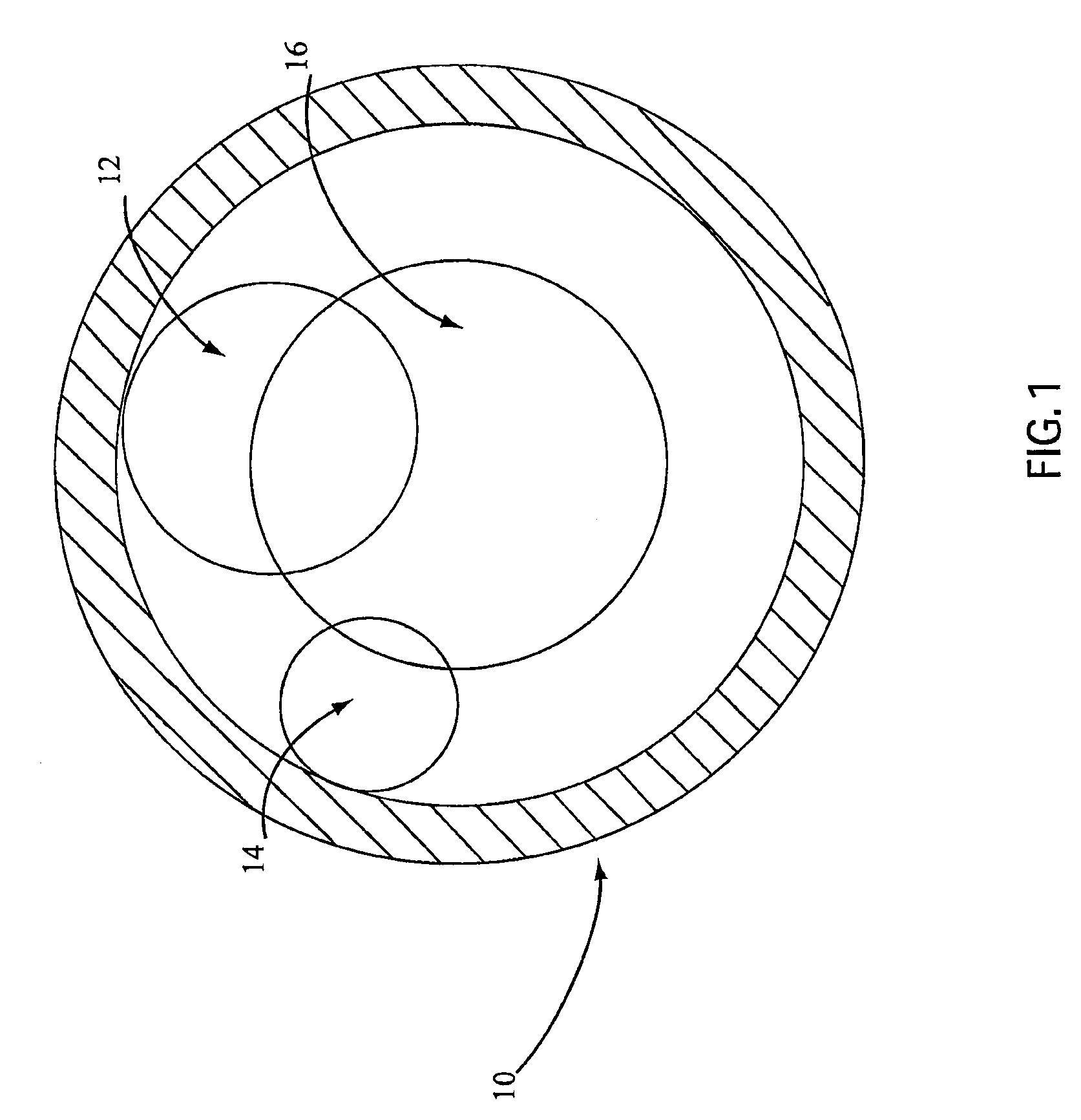
As can be seen, these lumens significantly interfere with each other.

Method used


Image

  • Embolic Protection Device Having Expandable Trap
  • Embolic Protection Device Having Expandable Trap
  • Embolic Protection Device Having Expandable Trap

Examples


embodiment 120

[0088]In operation, the valve embodiment 120 is actuated by longitudinally moving the guidewire 44 relative to the catheter wall 48. That is, pulling the guidewire 44 in a proximal direction relative to the catheter wall 48 causes the generally planar engagement surface 126 to sealably engage the abutment 121, which prevents fluid from flowing through the circular flow channel 128. Pushing the guidewire 44 in a distal direction relative to the catheter wall 48 causes the stopper 122 to disengage from the abutment 121, which allows fluid to flow through the circular flow channel 128.

[0089]Other valve embodiments 120 capable of being actuated by longitudinal motion are also within the scope of the present invention. For example, the stopper 122 may be rotated 180 degrees so that the conically shaped surface 124 engages the abutment 121, rather than the generally planar engagement surface 126. These embodiments may be desirable because the conically shaped surface 124 will self-center ...

embodiment 20

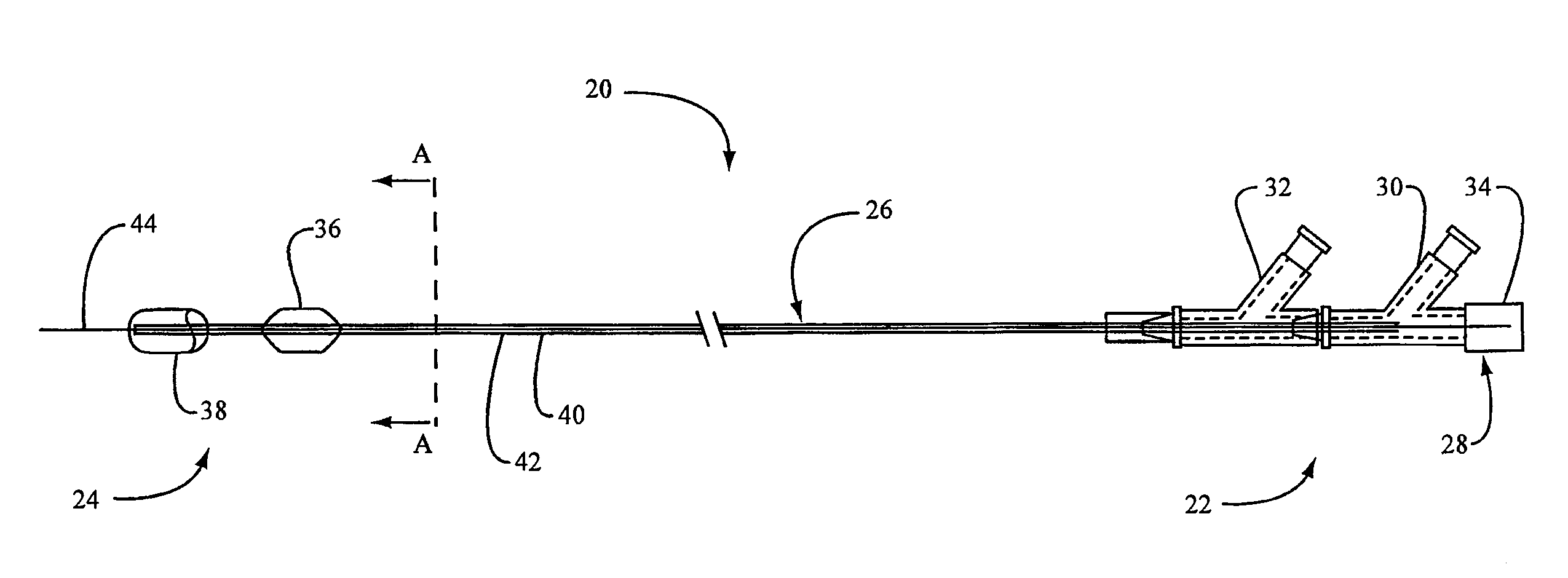
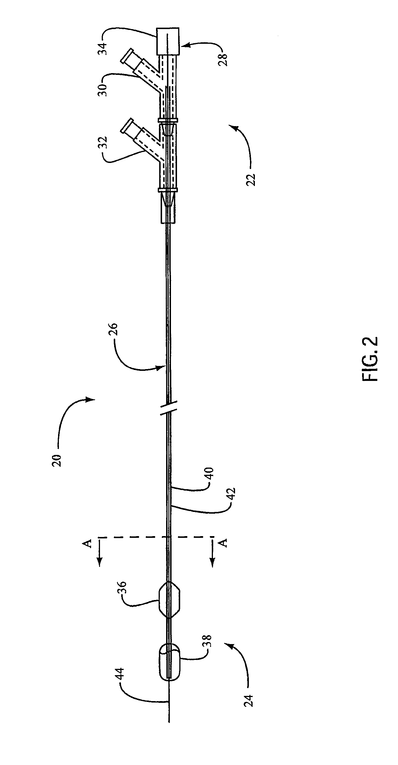
[0095]FIG. 18 is a sectional view of an angioplasty device 20 embodiment for use in retrograde applications (see FIG. 1 of U.S. Pat. No. 4,794,928 for conceptional orientation, which is herein incorporated by reference). This embodiment comprises a separate catheter 160 for the balloon 36 and for the inflation / deflation lumen 40. This catheter 160 has a first wall 162, a second wall 163, and an end wall or plug 164. In operation, the trap 38 in this embodiment is actuated by relative rotational and / or longitudinal motion between the exterior wall 46 and the first wall 162 of the catheter 160. Like the embodiments in FIGS. 14-17, this angioplasty device embodiment 20 can be loaded over a separate guidewire (not shown) or catheter (not shown) that has previously been inserted into the patient using lumen 150 and opening 152. Also like the embodiments in FIGS. 14-17, the trap 38 in this embodiment can be actuated using relative rotational motion or a combination of relative longitudina...

embodiment 38

[0096]FIG. 19 is a sectional view of an angioplasty device embodiment having a coupling device 190 with four radially spaced sockets 189. FIG. 20 is a sectional view of the coupling device 190. The coupling device 190 in this embodiment may be any device that prevents the balloon catheter 102 from rotating relative to the trap catheter bundle 100 (or translating, if used with the trap embodiment 38 described with reference to FIGS. 21 and 22). These embodiments are desirable because the trap catheter bundle 100 and the balloon catheter bundle 102 may be manufactured separately, then combined as needed.

[0097]FIG. 27 depicts an alternate embodiment in which a second group of struts 49a connect the coupling device 190 to an end 191 of the trap catheter bundle 100. In operation, the trap catheter bundles 100 in FIGS. 19 and 27 may be inserted over an in-place balloon catheter 102 and then either removed along with the balloon catheter 102 or by itself, depending on the configuration of ...


PUM


Abstract

An embolic protection device for use in medical, veterinary, non-medical or industrial applications where removal of an obstruction from a small diameter vessel or vessel-like structure could produce particles, which, if allowed to remain in the vessel, could cause undesirable complications and results. One embodiment comprises a catheter for insertion into a vessel and a trap operably connected to the catheter and to a rotatable member. Rotating the rotatable member relative to the catheter actuates the trap. One embodiment comprises a rotatable member that actuates a flexible strut between an arcuately expanded position and a helically twisted position, and a membrane operably connected to the flexible strut.

Description

CROSS-REFERENCE TO RELATED APPLICATION(S)[0001]This application is a divisional of U.S. patent application Ser. No. 12 / 105,909 filed on Apr. 18, 2008, which is a continuation of U.S. patent application Ser. No. 10 / 448,864, filed on May 30, 2003, which is a continuation of U.S. patent application Ser. No. 10 / 245,601, filed on Sep. 17, 2002, issued as U.S. Pat. No. 6,607,506 on Aug. 19, 2003, which is a continuation of U.S. patent application Ser. No. 10 / 133,031, filed on Apr. 26, 2002, issued as U.S. Pat. No. 6,485,456 on Nov. 26, 2002, which is a continuation of U.S. patent application Ser. No. 09 / 495,833, issued as U.S. Pat. No. 6,443,926 on Sep. 3, 2002, all of which are hereby incorporated by reference.FIELD OF THE INVENTION[0002]This invention relates to an angioplasty device for compressing and / or removing atherosclerotic plaques, thromboses, stenoses, occlusions, clots, potential embolic material and so forth (hereinafter “obstructions”) from veins, 15 arteries, vessels, ducts...

Claims


Application Information

Patent Timeline
Patent Type & Authority Applications(United States)
IPC IPC(8): A61M29/00A61B17/22A61M29/02
CPCA61B17/22032A61B17/221A61B2017/2212A61M2025/1093A61M2025/1015A61M2025/109A61M25/104
Inventor KLETSCHKA, HAROLD D.
Owner KLETABCHKA FOUND
Learn More