
Controller for Idle Stop System

a technology of controller and idle stop, which is applied in the direction of engine starters, machines/engines, instruments, etc., can solve the problems of reduced durability, large torque, wear of ring gears and pinion gears, etc., and achieves the improvement of durability, wear resistance, and quietness of the starter system. , the effect of smooth re-starting

Inactive Publication Date: 2011-07-14
HITACHI AUTOMOTIVE SYST LTD
View PDF10 Cites 10 Cited by
  • Summary
  • Abstract
  • Description
  • Claims
  • Application Information

AI Technical Summary

Benefits of technology

The present invention is about improving the behavior of an engine when it is started again after being stopped for a while. The invention uses a controller that detects the engine's revolution and adjusts the way the starter is driven accordingly. This helps to prevent damage to the engine and improves the overall performance of the starter system.

Problems solved by technology

In this case, in the state in which the angular acceleration direction of the engine revolution and the angular velocity direction of the pinion revolution differ from each other, the pinion gear collides with the ring gear at the engine side, and the collision torque becomes large, whereby there arise the problems of wear of the ring gear and the pinion gear at the time of connection, and reduction in durability.
Further, since the collision torque becomes large, there arises the problem that a collision sound of the ring gear and the pinion gear, and a mesh sound which occurs at the instant of connection become large.

Method used


Image

  • Controller for Idle Stop System
  • Controller for Idle Stop System
  • Controller for Idle Stop System

Examples


Embodiment Construction

[0027]Hereinafter, embodiments of the present invention will be described.

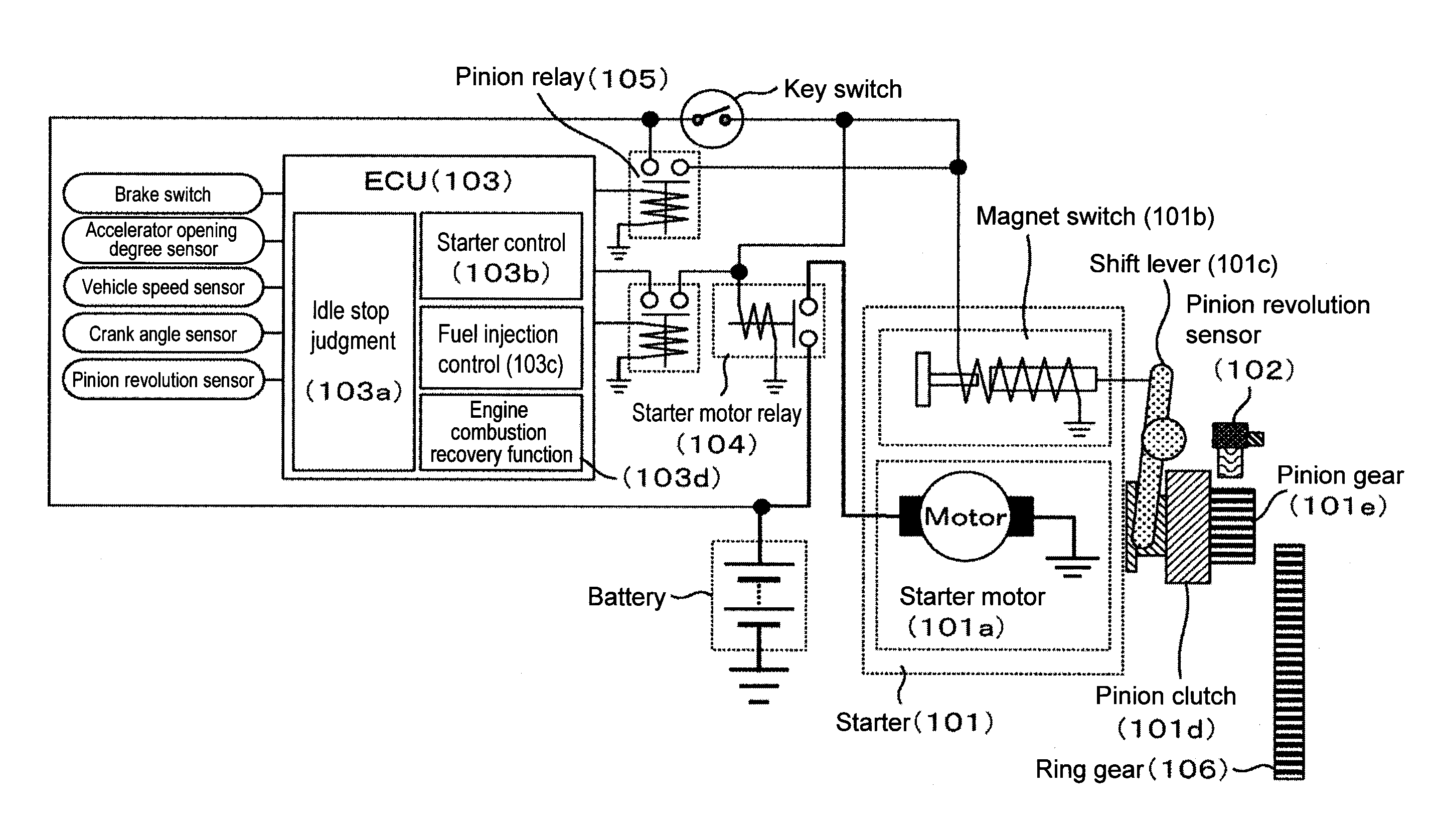
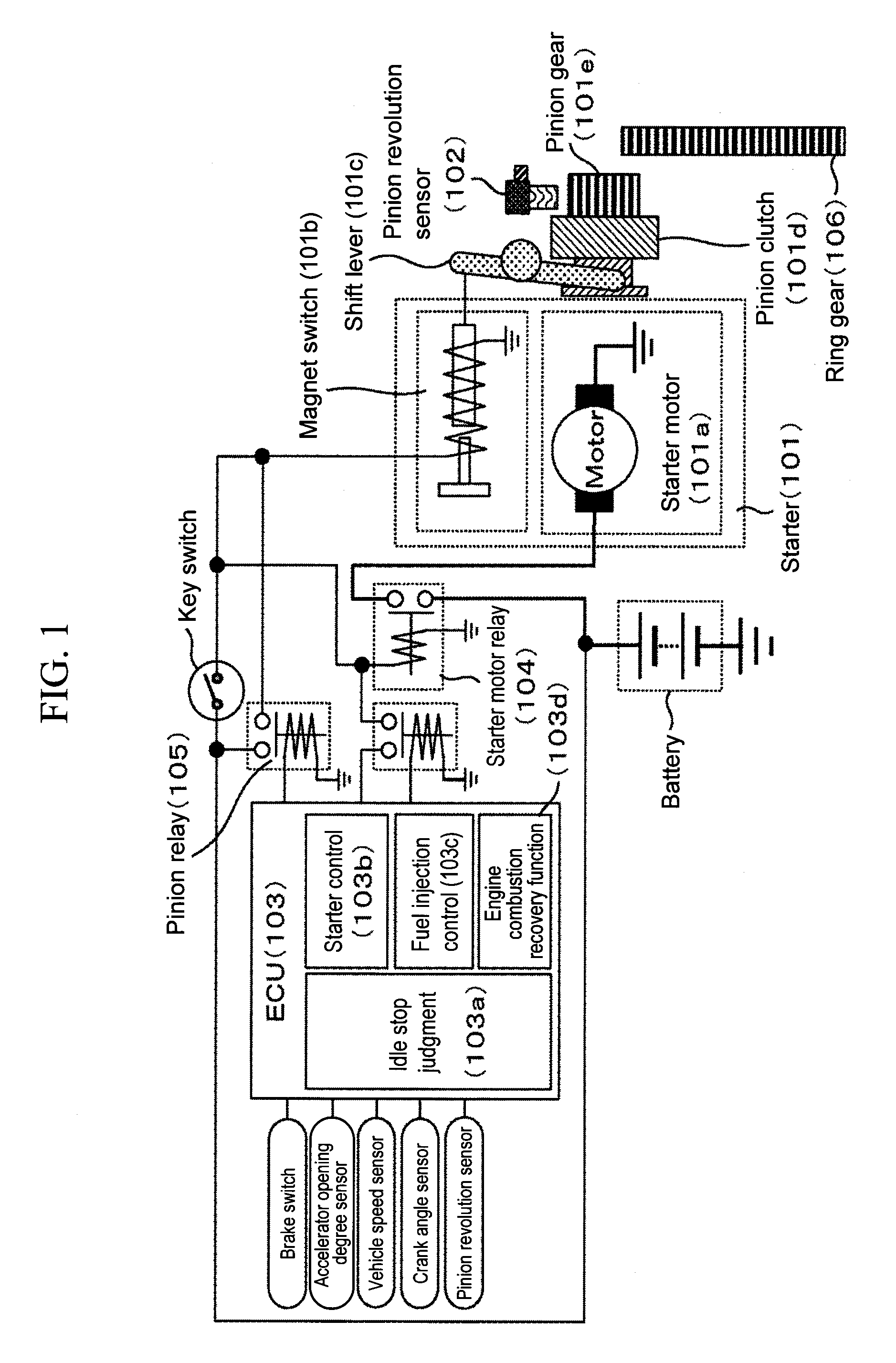
[0028]FIG. 1 is a functional block diagram of an idle stop system.

[0029]A starter main body 101 is configured by a starter motor 101a, a magnet switch 101b, a shift lever 101c, a pinion clutch 101d, a pinion gear 101e and the like. The starter motor 101a and the magnet switch 101b are driven by controlling power supply relays (of a starter motor relay 104 or a pinion relay 105) which are independent from each other, based on output from an ECU 103 (Engine Control Unit). The starter motor 101a and the pinion gear 101e are coaxially connected, and when the starter motor 101a rotates, the pinion gear 101e also rotates. When the magnet switch 101b is energized, the shift lever 101c is pushed out, and the pinion gear 101e is connected to a ring gear 106 which is included by an engine. The ring gear 106 rotates synchronously with a crankshaft of the engine which is not illustrated. Further, the ECU 103 implements id...


PUM


Abstract

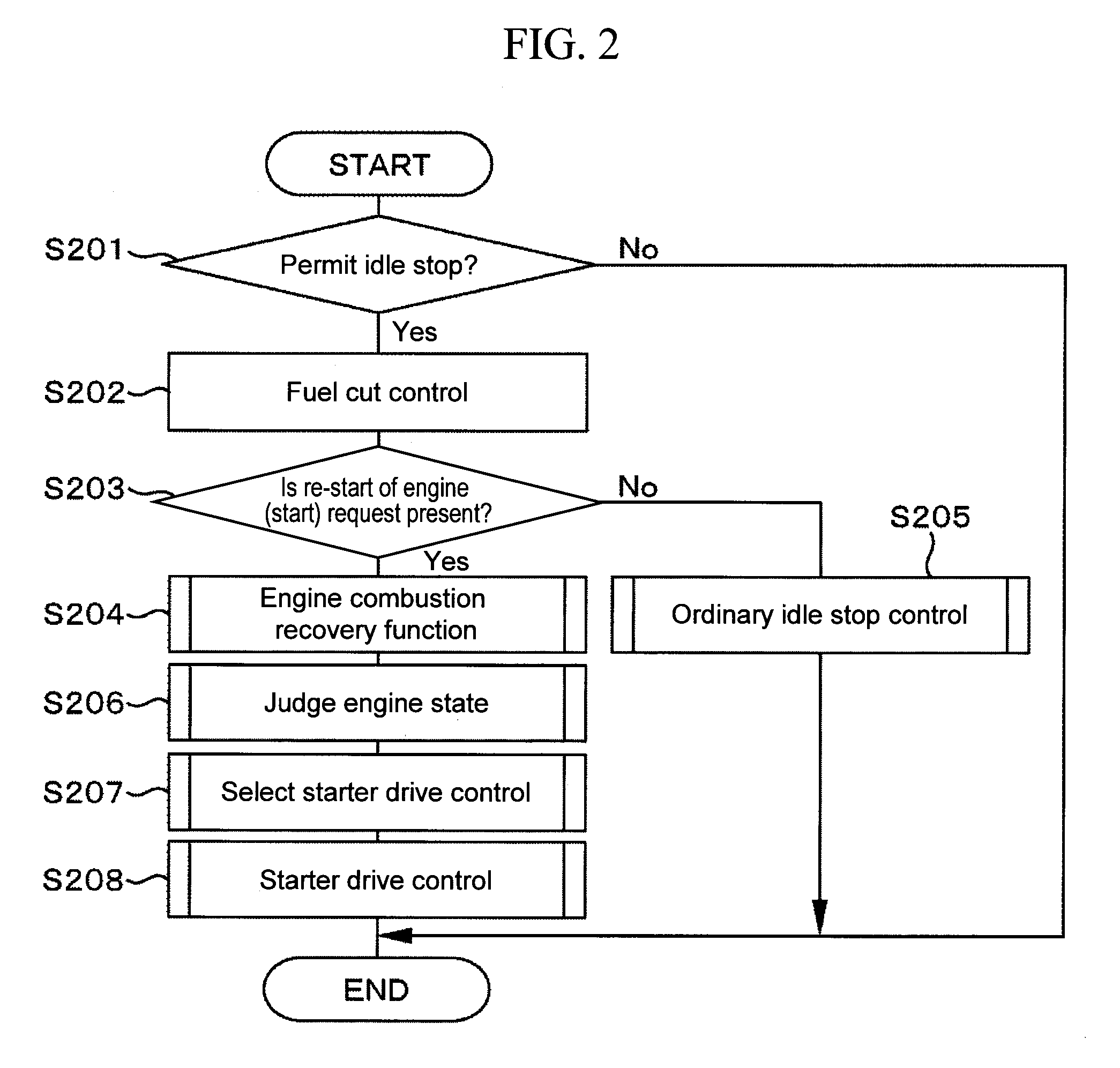
When a request for re-start of an engine or a request for start occurs during inertial revolution of the engine by fuel cut at the time of request for idle stop, an operation of starting by re-start of fuel injection and an operation of driving the starter overlap, and a problem is likely to occur in wear resistance and durability of a ring gear and a pinion gear. Further, since collision torque becomes large, a collision sound of the ring gear and the pinion gear and a mesh sound which occurs at the instant of connection are likely to occur. The present invention changes a method of starter drive based on a behavior of engine revolution after a request for re-start of the engine or a request for start occurs during inertial revolution of the engine by fuel cut at the time of request for idle stop, and combustion recovery is implemented by an engine combustion recovery function, or an engine state or the like at the time of occurrence of change of mind, in a controller of a vehicle having an idle stop function.

Description

BACKGROUND OF THE INVENTION[0001]1. Field of the Invention[0002]The present invention relates to a controller which automatically stops and re-starts an engine.[0003]2. Background Art[0004]Automatic stop of idling (idle stop) by cutting off the fuel to be supplied to an engine when predetermined conditions for allowing temporary stop of the engine are established during operation of an automobile is conceived of for the purpose of saving energy resources and environmental conservation, and the idle stop is already carried out in some automobiles.[0005]When in the automobile compliant with idle stop, the request for re-start of the engine (a request for re-start of the engine or a request for change of mind) occurs during an engine inertia revolution period after the fuel to be supplied to the engine is cut off by the request for idle stop which occurs when the aforementioned predetermined conditions are established until the crankshaft of the engine stops revolution, re-starting the...

Claims


Application Information

Patent Timeline
Patent Type & Authority Applications(United States)
IPC IPC(8): F02D28/00
CPCF02D35/023F02D2200/1012F02N11/0844F02N11/0855F02N11/0848F02N2200/022F02N2300/2002Y02T10/48F02N99/006Y02T10/40
Inventor MUKAIHARA, OSAMUMACHIDA, KENICHI
Owner HITACHI AUTOMOTIVE SYST LTD
Learn More