Photoelectric conversion module

Inactive Publication Date: 2011-07-21
SAMSUNG SDI CO LTD
View PDF13 Cites 10 Cited by
  • Summary
  • Abstract
  • Description
  • Claims
  • Application Information

AI Technical Summary

Benefits of technology

[0015]According to another aspect of embodiments of the present invention, in a photoelectric conversion module, it is not necessary to form holes in a substrate in order to inject an electrolyte into the substrate, and thus, fabrication costs of the substrate are reduced, and fabrication processes are simplified to increase production yield. In addition, degradation of rigidity of the substrate caused by holes in the substrate is avoided, and durability of the photoelec

Problems solved by technology

In addition, silicon or crystalline solar batteries formed as wafers using p-n junction of a semiconductor are widely d

Method used


Image

  • Photoelectric conversion module
  • Photoelectric conversion module
  • Photoelectric conversion module

Examples


Embodiment Construction

[0026]Some exemplary embodiments will now be described more fully hereinafter with reference to the accompanying drawings; however, embodiments of the present invention may be embodied in different forms and should not be construed as limited to the exemplary embodiments illustrated and set forth herein. Rather, these exemplary embodiments are provided by way of example for understanding of the invention and to convey the scope of the invention to those skilled in the art. As those skilled in the art would realize, the described embodiments may be modified in various different ways, all without departing from the spirit or scope of the present invention. Like reference numerals designate like elements throughout the specification and drawings.

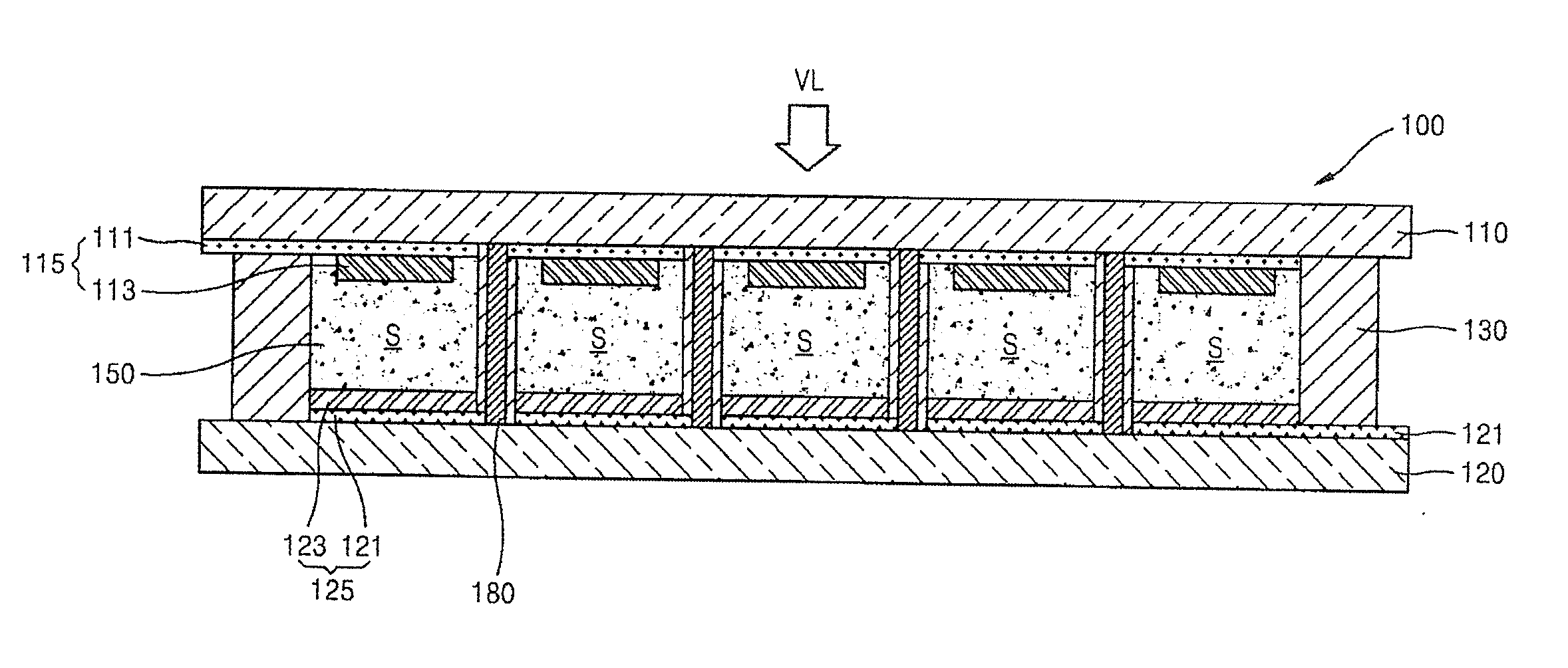
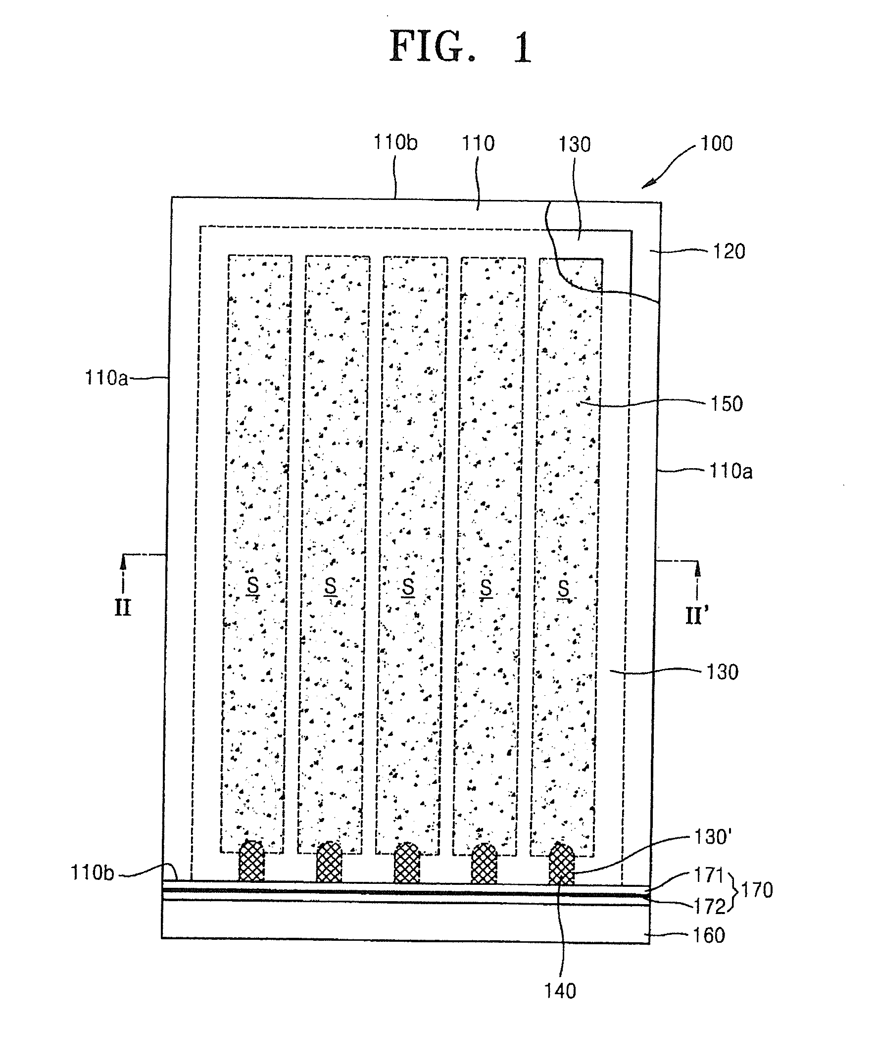
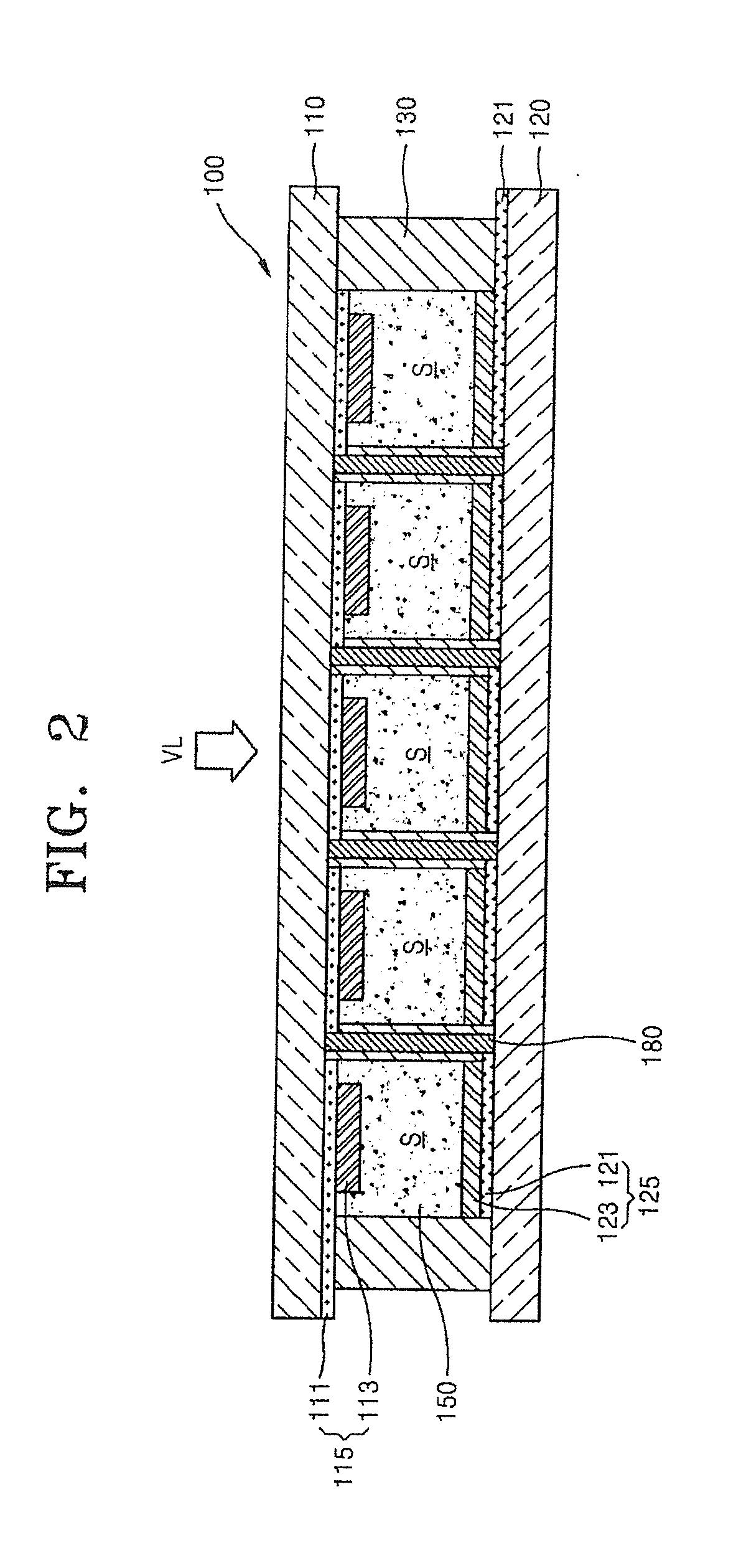
[0027]FIG. 1 shows a planar structure of a photoelectric conversion module 100 according to an embodiment of the present invention. Referring to FIG. 1, in one embodiment, the photoelectric conversion module 100 includes a plurality of photoele...


PUM


Abstract

A photoelectric conversion module including a first substrate; a second substrate spaced apart from the first substrate in a first direction; a plurality of photoelectric cells between the first and second substrates, each including an electrolyte; and a sealing member between the first and second substrates, the sealing member surrounding the plurality of photoelectric cells and extending between adjacent photoelectric cells of the plurality of photoelectric cells, wherein the sealing member has at least one electrolyte injecting portion for receiving the electrolyte into the photoelectric cells.

Description

CROSS-REFERENCE TO RELATED APPLICATION[0001]This application claims priority to and the benefit of U.S. Provisional Application No. 61 / 296,421, filed on Jan. 19, 2010 in the United States Patent and Trademark Office, the entire content of which is incorporated herein by reference.BACKGROUND[0002]1. Field[0003]Aspects of embodiments of the present invention relate to a photoelectric conversion module, and more particularly, to a photoelectric conversion module having a structure for sealing electrolyte.[0004]2. Description of the Related Art[0005]Recently, various research has been conducted in the area of photoelectric conversion modules that convert optical energy into electric energy as a source of energy that may substitute for fossil fuel, and solar batteries using solar light have been identified.[0006]Research about solar batteries operating in various ways has been conducted. In addition, silicon or crystalline solar batteries formed as wafers using p-n junction of a semicond...

Claims


Application Information

Patent Timeline
IPC IPC(8): H01L31/042
CPCH01G9/2031Y02E10/542H01G9/2077H01G9/2059Y02P70/50
Inventor YANG, NAM-CHOULLEE, JONG-KIKIM, SUNG-SU
Owner SAMSUNG SDI CO LTD
Why Eureka
Try Eureka