
Bottom hole assembly with ported completion and methods of fracturing therewith

a technology of fracturing and assembly, which is applied in the direction of hose connection, borehole/well accessories, sealing/packing, etc., can solve the problems of consuming more fluid, fracturing through holes, and affecting the fracturing process, so as to improve the fracture treatment

Active Publication Date: 2011-07-21
BAKER HUGHES INC
View PDF51 Cites 43 Cited by
  • Summary
  • Abstract
  • Description
  • Claims
  • Application Information

AI Technical Summary

Benefits of technology

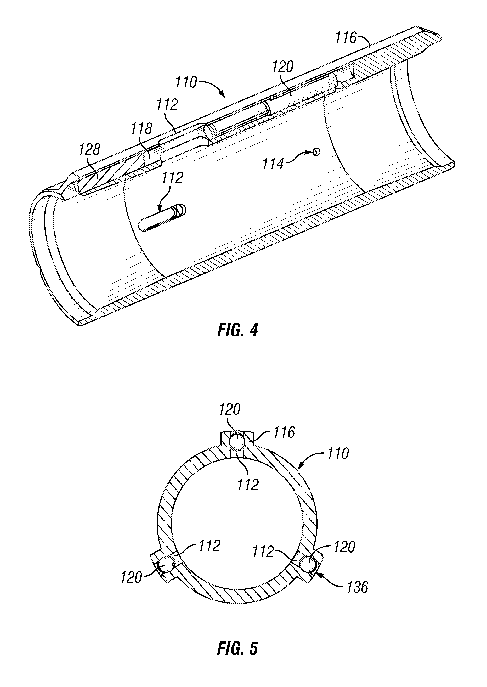
[0019]The valve may be configured to move between the open and closed positions upon the application of a pressure differential between the fracture ports and the valve vent hole. The valve may be a sleeve that encircles the perimeter of the mandrel. The housing may include a fill port adapted for the injection of grease into the annulus. In the instance the housing is a composite of a valve housing and vent housing, the valve housing and the vent housing may each include a fill port adapted for the injection of grease into the annulus. The injection of grease into the annulus may prevent the ingress of cement into the annulus during the process of cementing the collar into a wellbore. The mandrel may include a burstable device positioned within the valve vent hole to selectively prevent fluid communication between the inner flow path and the annulus. The mandrel may include a plurality of valve vent holes with one of the valve vent holes having a reduced diameter compared to the rest. The reduced diameter may be ⅛th inch and the reduced diameter may prevent the ingress of cement into the annulus. The mandrel may further include at least one secondary valve vent hole located uphole from the primary valve vent holes.
[0023]In one embodiment, the differential pressure at which the valve is opened can be set higher than the pressure required to initiate a fracture in the reservoir. In this way energy can be stored in the fluid contained in the well. The stored energy in the fluid can be used to improve the fracture treatment, as the energy in the fluid can be applied to the reservoir in a shorter period of time as compared to the power available from the pumps through the completion.

Problems solved by technology

Then fracturing can occur through the holes.
One of the issues with sand jet perforating is that sand from the perforating process can be left in the well bore annulus and can potentially interfere with the fracturing process.
Another issue with sand jet perforating is that more fluid is consumed to cut the perforations and either circulate the excess solid from the well or pump the sand jet perforating fluid and sand into the zone ahead of and during the fracture treatment.
Cleaning the sand from such a large number of zones can add significant processing time, require the excessive use of fluids, and increase the cost.
The excessive use of fluids may also create environmental concerns.
However, because the well diameter is limited in size and the ball sizes are typically increased in quarter inch increments, this process is limited to fracturing only about 11 or 12 zones in a well before ball sizes run out.
In addition, the use of the sliding sleeve assemblies and the packers to set the well casing in this method can be costly.
Further, the sliding sleeve assemblies and balls can significantly reduce the inner diameter of the casing, which is often undesirable.
As in the case of the packers-plus-style completion, the sliding sleeve assemblies and the packers to set the well casing in this method can be costly.
Further, the sliding sleeve assemblies can undesirably reduce the inner diameter of the casing.
In addition, the sleeves are prone to failure due to high velocity sand slurry erosion and / or sand interfering with the mechanisms.

Method used


Image

  • Bottom hole assembly with ported completion and methods of fracturing therewith
  • Bottom hole assembly with ported completion and methods of fracturing therewith
  • Bottom hole assembly with ported completion and methods of fracturing therewith

Examples


Embodiment Construction

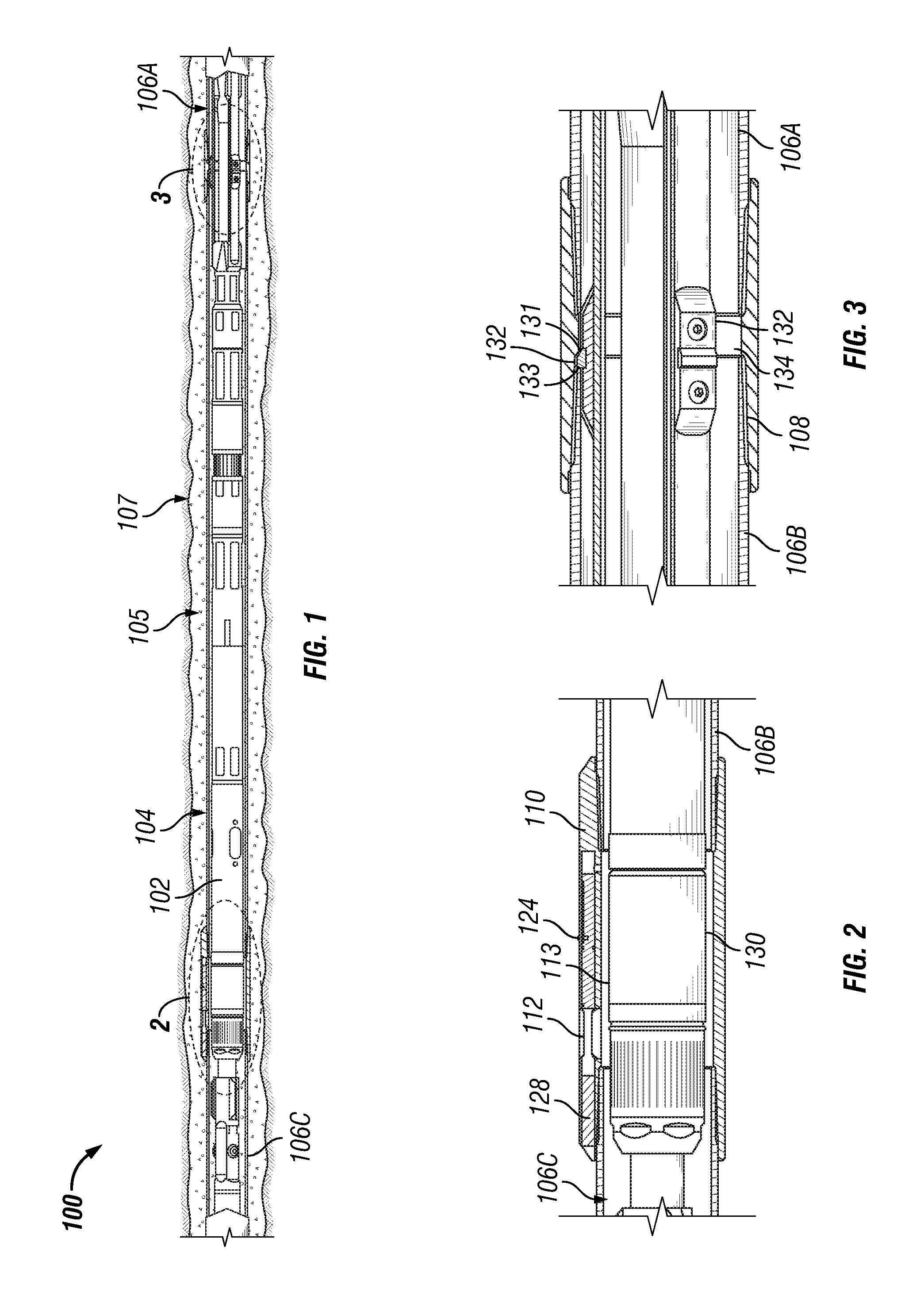
[0043]FIG. 1 illustrates a portion of a wellbore completion 100, according to an embodiment of the present disclosure. Wellbore completion 100 includes a bottom hole assembly (“BHA”) 102 inside a casing 104. Any suitable BHA can be employed. In an embodiment, the BHA 102 can be designed for carrying out fracturing in a multi-zone well. An example of a suitable BHA is disclosed in copending U.S. patent application Ser. No. 12 / 626,006, filed Nov. 25, 2009, in the name of John Edward Ravensbergen and entitled, COILED TUBING BOTTOM HOLE ASSEMBLY WITH PACKER AND ANCHOR ASSEMBLY, the disclosure of which is hereby incorporated by reference in its entirety.

[0044]As more clearly illustrated in FIGS. 2 and 3, casing 104 can include multiple casing lengths 106A, 106B and 106C that can be connected by one or more collars, such as collars 108 and 110. Casing lengths 106A, 106B, and / or 106C may be pup joints, segments of casing approximately six (6) feet in length, which may be configured to aid ...


PUM

PropertyMeasurementUnit
lengthaaaaaaaaaa
pressuresaaaaaaaaaa
pressuresaaaaaaaaaa

Abstract

A ported completion and method for use in fracturing multi-zone wells. A casing assembly having a plurality of casing lengths and one or more collars positioned so as to couple together the casing lengths. The collars may be a tubular body having an inner flow path, one or more fracture ports configured to provide fluid communication between an outer surface of the collar and the inner flow path, one or more valve holes intersecting the fracture ports, one or more valve vent holes positioned to provide fluid communication between the valve holes and the inner flow path, and one or more valves positioned in the valve holes for opening and closing the fracture ports. The valves are configured to open when a pressure differential is created between the fracture ports and the valve vent holes. The valve vent hole may be an annulus around the perimeter of the tubular body.

Description

RELATED APPLICATIONS[0001]The present disclosure claims the benefit of U.S. Provisional Patent Application No. 61 / 228,793 entitled “BOTTOM HOLE ASSEMBLY WITH PORTED COMPLETION AND METHODS OF FRACTURING THEREWITH” by John Edward Ravensbergen filed on Jul. 27, 2009, which is hereby incorporated by referenced in its entirety.BACKGROUND[0002]1. Field of the Disclosure[0003]The present disclosure relates generally to a downhole tool for use in oil and gas wells, and more specifically, to a ported completion that can be employed for fracturing in multi-zone wells.[0004]2. Description of the Related Art[0005]Oil and gas well completions are commonly performed after drilling hydrocarbon producing wellholes. Part of the completion process includes running a well casing assembly into the well. The casing assembly can include multiple lengths of tubular casing attached together by collars. A standard collar can be, for example, a relatively short tubular or ring structure with female threads a...

Claims


Application Information

Patent Timeline
Patent Type & Authority Applications(United States)
IPC IPC(8): E21B43/26F16L25/00
CPCA61K48/0025A61K48/0041E21B2034/007E21B43/26E21B34/102E21B2200/06
Inventor RAVENSBERGEN, JOHN EDWARDLAUN, LYLE E.
Owner BAKER HUGHES INC
Learn More