
Ocean wave energy extractor

a technology of energy extractor and ocean wave, which is applied in the direction of electric generator control, machines/engines, mechanical equipment, etc., can solve the problems of increasing maintenance costs, damage to sensitive components, and limitations of such devices, and achieve the effect of protecting sensitive components

Inactive Publication Date: 2011-07-21
PATTEN KENNETH SYKES
View PDF19 Cites 5 Cited by
  • Summary
  • Abstract
  • Description
  • Claims
  • Application Information

AI Technical Summary

Benefits of technology

"The patent describes an ocean wave energy extractor that can generate energy from ocean waves without needing to be moored to a seabed or land. The extractor includes a flotation device with a mechanism for extracting energy, which is protected from damage by the flotation device. The extractor can be designed in a spherical or cylindrical shape, and can be oriented in different directions to maximize energy capture. The technical effect of this invention is that it provides a reliable and efficient way to extract energy from ocean waves, minimizing damage and deterioration caused by the ocean."

Problems solved by technology

Several limitations exist with such devices.
These devices often include components and materials that are sensitive to salinity of ocean water and tend to deteriorate, resulting in increased maintenance costs.
Ocean climate is volatile and areas of the ocean are often subject to extreme weather conditions that may damage sensitive components exposed to the ocean water.
Mooring these devices tend to increase manufacturing and maintenance costs, and mooring requirements limit where these devices can be deployed.

Method used


Image

  • Ocean wave energy extractor
  • Ocean wave energy extractor
  • Ocean wave energy extractor

Examples


Embodiment Construction

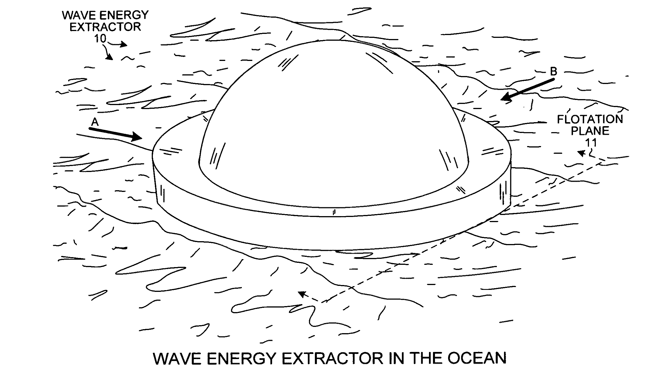
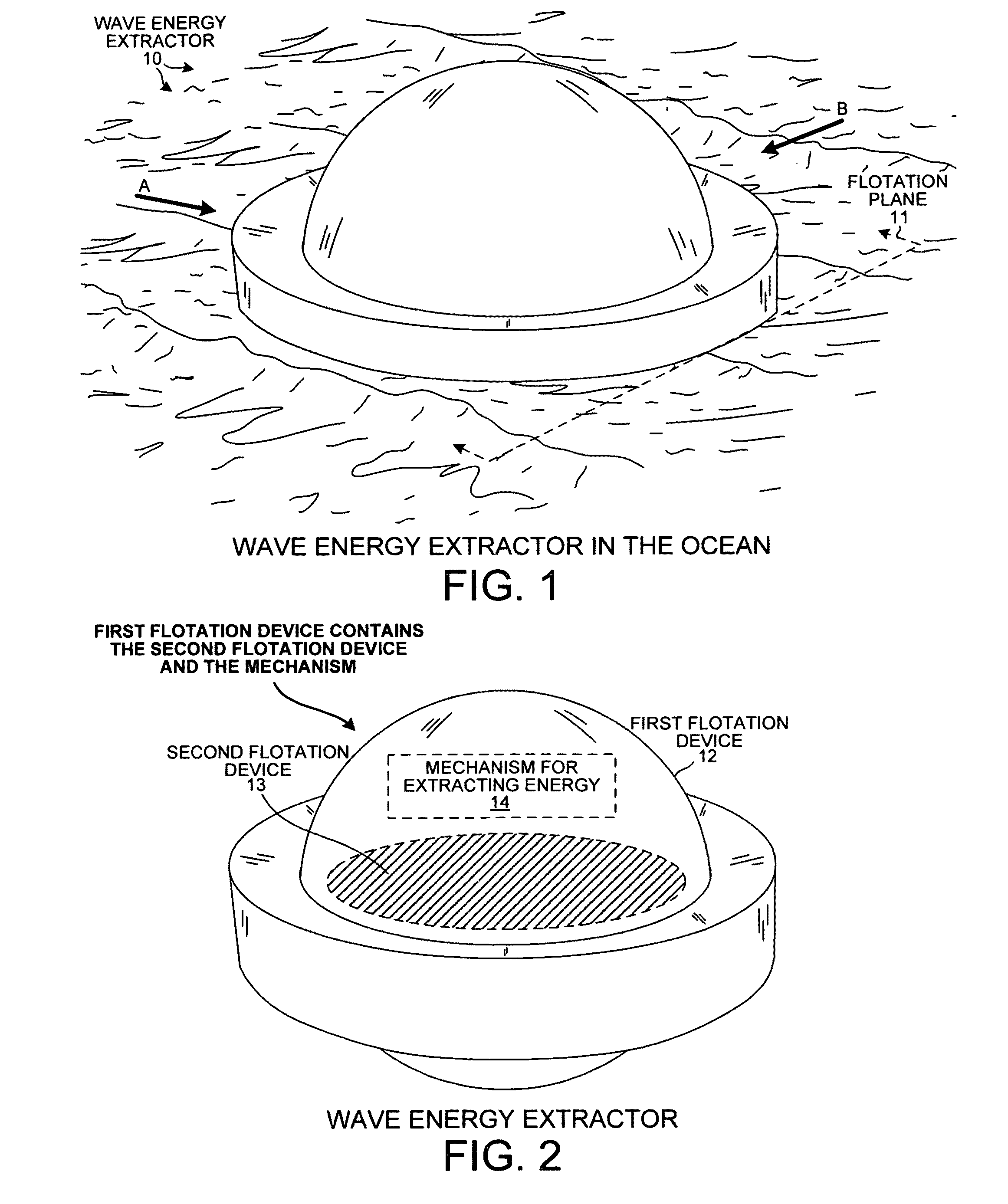
[0025]FIG. 1 is a diagram of a perspective view of an ocean wave energy extractor 10 floating on an ocean surface in accordance with one novel aspect. Wave energy extractor 10 floats on flotation plane 11 and extracts energy from propagating waves. This energy extracted from waves is converted into electrical energy that can be supplied onto a power grid. An incoming wave rotates the wave energy extractor relative to an inner device, and this relative rotation engages a mechanism that generates electrical energy, such as a piston. In this example, wave energy extractor 10 is approximately forty-two feet in diameter. If wave energy extractor 10 is deployed in an ocean region with swells approximately ten feet high with a period of eight seconds (or in other words, ten foot waves passing every eight seconds), then wave energy extractor 10 can generate approximately 210 kW of power.

[0026]During operation, wave energy extractor 10 does not need to be moored to a fixed location (such as ...


PUM


Abstract

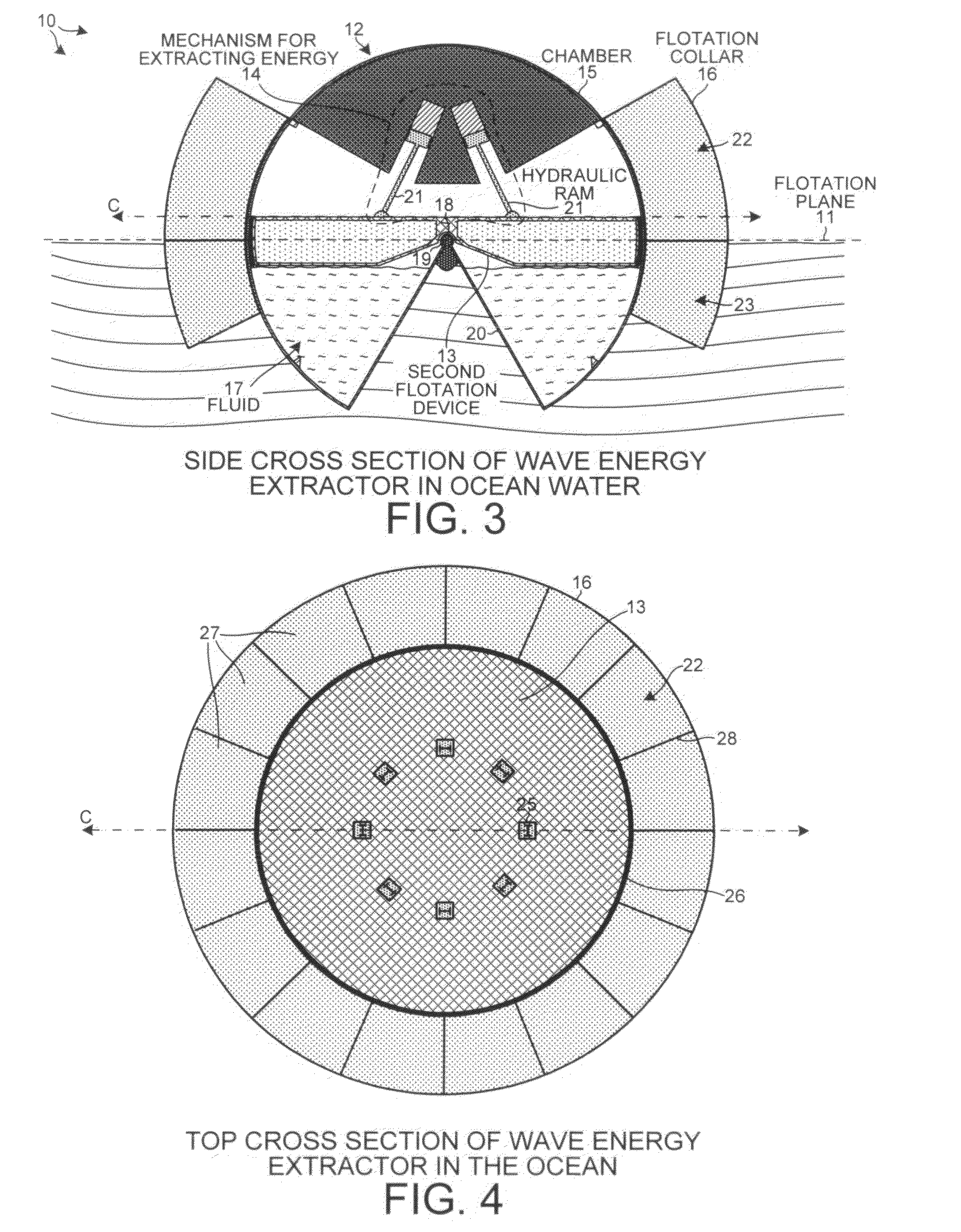
An ocean wave energy extractor includes a first flotation device that contains a second flotation device and a mechanism for extracting energy. The wave energy extractor floats in seawater and extracts energy from waves. A propagating wave rotates the first flotation device relative to the second flotation device. The mechanism is connected to both flotation devices and generates energy from this relative rotation. In one example, a first flotation device includes a spherical chamber with a flotation collar, and a second flotation device supported by a joint at a center of the chamber. A wave approaching from any direction rotates the first flotation device relative to the second flotation device, and a mechanism for extracting energy generates electrical energy from the relative rotation. The chamber shields inner components from seawater and adverse ocean conditions. The wave energy extractor need not be moored to a location to extract energy from waves.

Description

CROSS REFERENCE TO RELATED APPLICATION[0001]This application claims the benefit under 35 U.S.C. §119 of provisional application Ser. No. 61 / 336,160, entitled “A Device For Exploiting Ocean Wave Power”, filed Jan. 19, 2010. The subject matter of provisional application Ser. No. 61 / 336,160 is incorporated herein by reference.TECHNICAL FIELD[0002]The described embodiments relate to extracting energy from ocean waves.BACKGROUND INFORMATION[0003]Ocean wave energy extractors are devices used to extract energy from ocean waves. These devices usually convert the extracted energy into electrical energy that is supplied to a power station. Such devices typically include a power take-off system and two components, one component that is fixed and a second component that moves relative to the fixed component. These devices generate electric energy from a relative displacement between the first and second components. For example, an incoming wave displaces the second component relative to the fir...

Claims


Application Information

Patent Timeline
Patent Type & Authority Applications(United States)
IPC IPC(8): F03B13/20
CPCF03B13/20Y02E10/38F05B2240/93Y02E10/30F05B2250/44
Inventor PATTEN, KENNETH SYKES
Owner PATTEN KENNETH SYKES
Learn More