Modular sealed portable digital electronic controller

a digital electronic controller and module sealing technology, applied in the direction of electrical apparatus construction details, electrical apparatus casings/cabinets/drawers, instruments, etc., can solve the problems of destroying the ac power connector and related circuitry, and affecting the operation of the electronic controller

Inactive Publication Date: 2011-01-27
WEIGH TECH
View PDF49 Cites 0 Cited by
  • Summary
  • Abstract
  • Description
  • Claims
  • Application Information

AI Technical Summary

Benefits of technology

[0016]It is therefore an object of the present invention to provide a digital electronic controller, such as a load cell indicator, that is particularly suited for use in a harsh washdown environment.
[0017]It is a further object of the present invention to provide a load cell indicator of the above type that protects many key, sensitive components of the indicator by permanently sealing them within a watertight enclosure such as by using an adhesive seal.
[0018]It is a further object of the present invention to provide a load cell indicator of the above type that protects against moisture coming into contact with high voltage within the indicator.

Problems solved by technology

Most have common weaknesses that present problems particularly when the load cell indicators are used in rough, washdown environments.
This high pressure spray will often seep past gaskets and seals, leaving the internal electrical connectors and electronic components wet.
Since the cleaning solutions used are typically slightly conductive, any solution that finds its way to the incoming AC power connector will often result in damage, which can range from minor corrosion of wiring and printed circuit board traces to arc-over and destruction of the AC power connector and related circuitry.
This damage often limits the useful life of an instrument to mere weeks.
If the indicator uses a plastic membrane keypad, which is by far the most common type of front panel found on load cell indicators, this activity will quickly result in a damaged keypad.
Depending on the design on the specific indicator, a damaged keypad may be replaced, or it may mean replacement of the entire indicator.
Again, this potential for damage limits the lifetime of indicators in some environments.
While this style of double enclosure mounting may reduce high pressure fluid infiltration in the indicator enclosure, it also limits operator access to the indicator, sometimes excessively so.
The effectiveness of this mounting style is frequently reduced by the tendency of operators to forget to latch the front lid, leaving the indicator exposed to the very high pressure spray the lid was intended to prevent.
The choice of display can be problematic, as many display types with outstanding visibility (such as a vacuum florescent display—VFD) have high power consumption.
Indicators that use VFDs often have no provision for running from battery power, limiting their usefulness as a portable device.
Other indicators use seven-segment light emitting diode (LED) displays, which provide good visibility and reasonable power consumption, but the seven-segment style of digit is not conducive to presenting alphanumeric data to the user.
Indicators with seven segment displays are thus limited in displaying information, which makes setup and troubleshooting cryptic and difficult.
However, many digital load cell indicators use LCD modules that require ambient light for the display to be visible to the user, which makes the instrument difficult to use in dark or uncertain lighting.
High temperature washdown followed by extended use in cold temperature environments can lead to condensation forming on the enclosure.
If the seals around the cables, display, and keypad are less than perfect, and they usually are, condensation can also form on the inside of the enclosure, which can wet the electronic components, circuit boards, and connectors.
Display fogging is also common in this situation.
These conditions conspire to limit the effectiveness of the indicator.
If internal access to the enclosure is desired, such as to replace a load cell cable or power cable, the technician performing the procedure will spend quite a bit of time and frustration removing all the fasteners and sealing material to gain access to the internal connections of the indicator.
This limitation leads to the use of external hardware, such as summing boxes, to condition multiple load cell signals (as might be provided by a large tank or platform scale) for use with common indicators.
For many load cell indicators, this is simply not possible, as there is no allowance for field customization of the software code contained inside the indicator controller, and the manufacturers are unable to update software once the indicator has been manufactured.
During integration and testing, problems, bugs, or unforeseen circumstances will often arise that require the machine controller software to be modified.
If the advanced load cell indicator / controller is not designed with this in mind, the upgrade might require significant disassembly of the indicator and associated hardware to replace a physical electronic device containing the controller software.
This requirement limits the overall size and weight of the instrument and also requires a portable power source, such as a battery.
Some do, but require so much power that the only practical option is a physically large battery mounted external to the indicator enclosure.
Any externally mounted battery will require wiring to provide power to the indicator, and that wiring introduces at least two additional weaknesses into the system: the wiring must be sealed to prevent leakage where it enters the indicator enclosure, and exposed wiring is vulnerable to damage.
Load cell indicators used in harsh environments are often damaged.
When this occurs, many users will desire to troubleshoot the indicator to determine the cause of the failure, and then will often elect to attempt a repair.
Load cell indicators are relatively complicated and include delicate electronic instruments, so troubleshooting may call for the use of skilled electronic technicians and other highly trained and costly personnel equipped with an assortment of specialized tools.
A user or technician who may attempt troubleshooting but who may lack the proper training or the right tools can often do more harm than good when provided with ready access to all of the electronic components of these relatively complex, delicate instruments.
Many load cell indicators are difficult to calibrate.
Some indicators have a rather lengthy and complicated calibration procedure that is not obvious without supplemental documentation, so if the calibration procedure instructions are misplaced, that scale is unusable.

Method used


Image

  • Modular sealed portable digital electronic controller
  • Modular sealed portable digital electronic controller
  • Modular sealed portable digital electronic controller

Examples


Embodiment Construction

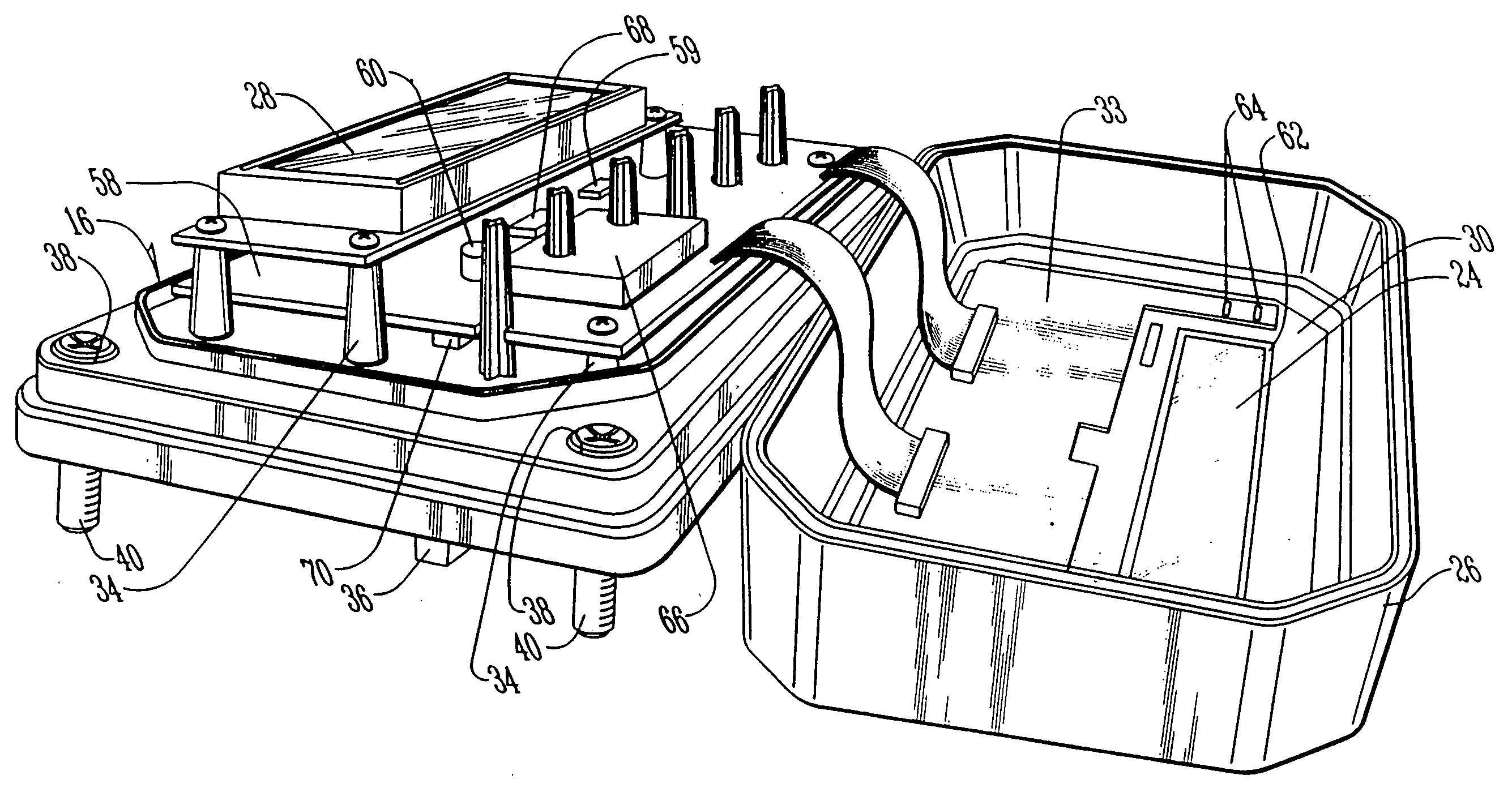
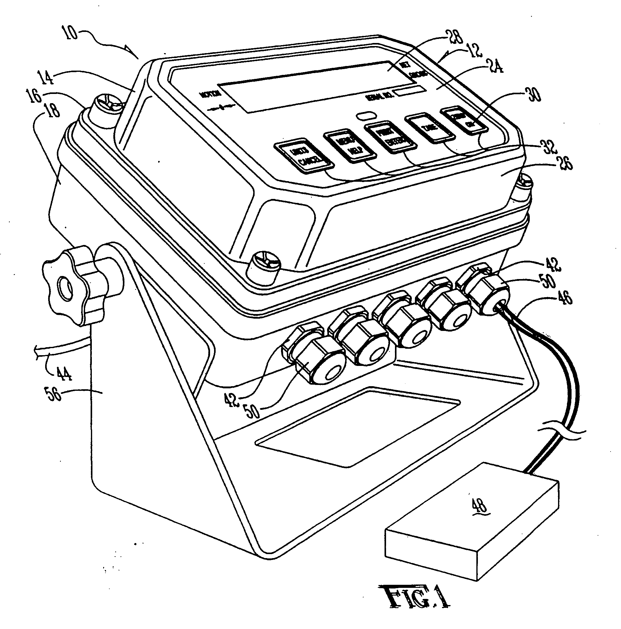
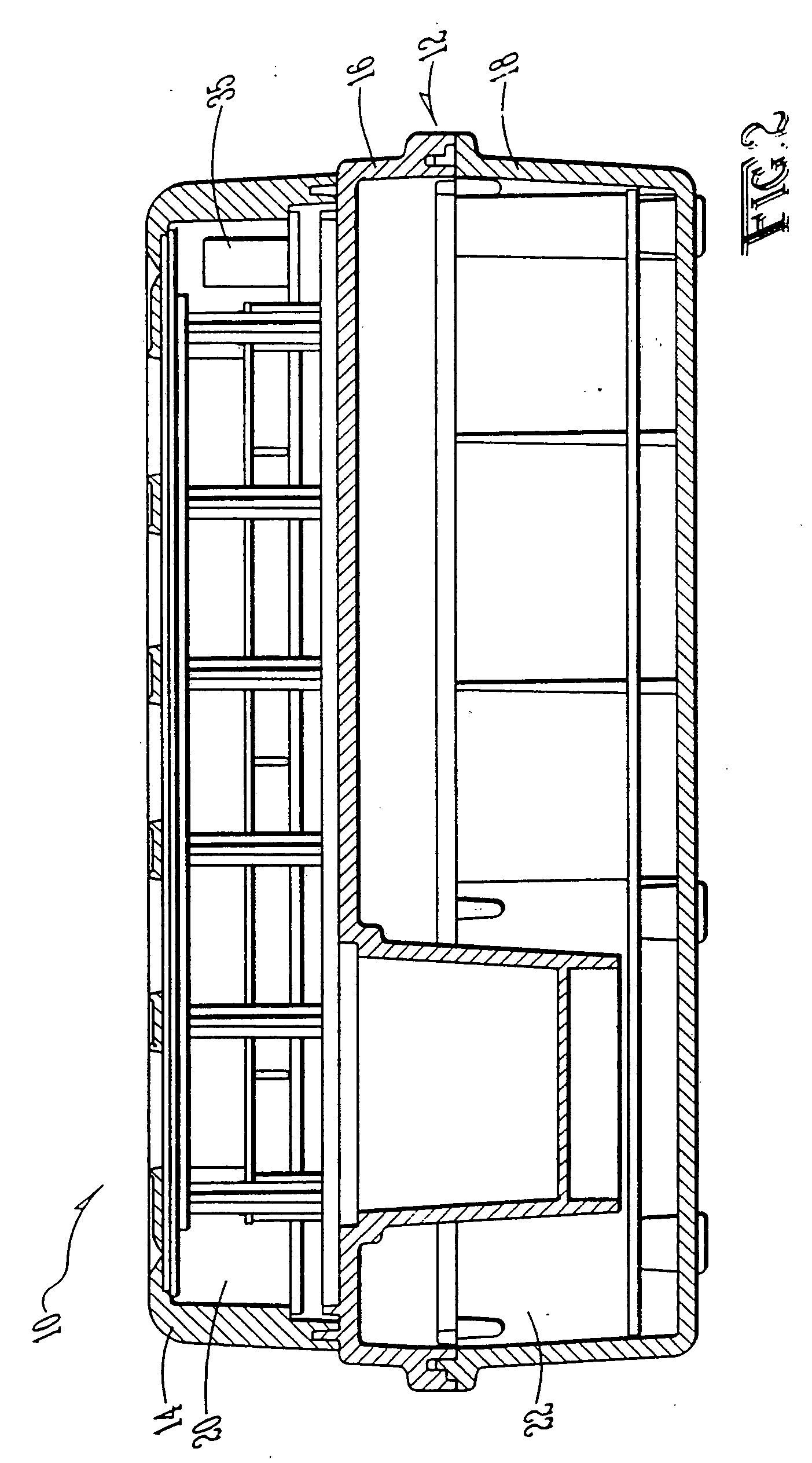
[0038]Referring to FIG. 1, the reference numeral 10 refers in general to an electronic digital controller, such as a load cell indicator, of the present invention. The indicator 10 has a housing 12 comprised of a front cover 14, a base 16, and a rear cover 18 that are formed from molded plastic and that fit together to form front and rear enclosures 20 and 22 that house various components of the indicator 10.

[0039]The front cover 14 is formed by a front panel 24 and a side panel or bezel 26. The front panel 24 is produced from a transparent, rigid plastic to allow a display 28 and front panel legends 30 to be visible from outside the enclosure. The front panel 24 also has one or more areas of reduced thickness 32 aligned with keys or touch sensitive areas of a keypad 33 disposed inside the front enclosure 20. The areas of reduced thickness 32 are formed integrally with the remaining portion of the front panel 24 and are also rigid. The front panel 24 is bonded, such as by adhesive b...


PUM


Abstract

An electronic digital controller, such as a load cell indicator, is disclosed in which a number of components, such as a circuit board, display, and keypad are placed within an enclosure, and the enclosure is bonded closed, such as using an adhesive, to render the enclosure watertight. The keypad is a touch sensitive, capacitive keypad with no moving parts, and it is housed behind a rigid panel. An optoelectronic transceiver allows for data exchange with an electronic memory device housed in the adhesively sealed enclosure and allows for data exchange and for updating or modification of software code housed therein. Other components, such as another circuit board, a power supply, and block connectors, are placed in an adjacent enclosure, and the circuit boards in the two enclosures are electrically connected. The power supply is preferably a potted AC power supply but may also include a battery.

Description

CROSS-REFERENCE TO RELATED APPLICATIONS[0001]This application is a continuation of co-pending U.S. patent application Ser. No. 12 / 154,914 filed on May 28, 2008 and having the inventors Timothy R. Cox, et al., which is a continuation of U.S. patent application Ser. No. 11 / 198,110 filed on Aug. 5, 2005 and having the inventors Timothy R. Cox, et al., now U.S. Pat. No. 7,397,003 issued on Jul. 8, 2008, which is a divisional of U.S. patent application Ser. No. 10 / 345,566 filed Jan. 16, 2003, now U.S. Pat. No. 7,002,084 issued on Feb. 21, 2006, which claims benefit of U.S. Provisional Patent Application Ser. No. 60 / 350,297 filed Jan. 16, 2002. Each of the aforementioned related patent applications and patents is herein incorporated by reference.BACKGROUND OF THE INVENTION[0002]This invention relates to digital electronic controllers and, more particularly, to portable digital electronic load cell indicators.[0003]Measuring transducers are known in the art and are used to measure forces a...

Claims


Application Information

Patent Timeline
Patent Type & Authority Applications(United States)
IPC IPC(8): G01G21/28G06F1/16H05K5/06
CPCH05K5/06G01G21/28
Inventor COX, TIMOTHY R.PAGAN, RONALD T.NEWELL, STEPHEN S.TULL, STEVE D.
Owner WEIGH TECH
Why Eureka
Try Eureka