
Dental tools for guided surgery

a technology for guided surgery and dental tools, applied in boring tools, medical science, dentistry, etc., can solve the problems of affecting the smooth insertion and removal of the tool, affecting the precision of the guided surgery, etc., and achieve the effect of preventing abrasion of the marks and good readability

Active Publication Date: 2011-07-21
STRAUMANN HLDG AG
View PDF24 Cites 36 Cited by
  • Summary
  • Abstract
  • Description
  • Claims
  • Application Information

AI Technical Summary

Benefits of technology

[0014]It is therefore a problem addressed by the present invention to improve the outlined features of existing surgical tools. Specifically, the invention aims to prevent abrasion of the marks during usage, cleaning or sterilisation to ensure good readability even after multiple employments, and obtain smooth guidance of the guide portion when inserted in the guide channel.

Problems solved by technology

A continuous recess, stretching 360° about the guide portion, could result in the tool catching on the guide element, thus affecting the smooth insertion and removal of the tool.
Further, it is possible that a continuous recess would result in the tool entering the drill site at a slight angle, thus affecting the precision of the guided surgery.

Method used


Image

  • Dental tools for guided surgery
  • Dental tools for guided surgery
  • Dental tools for guided surgery

Examples


Embodiment Construction

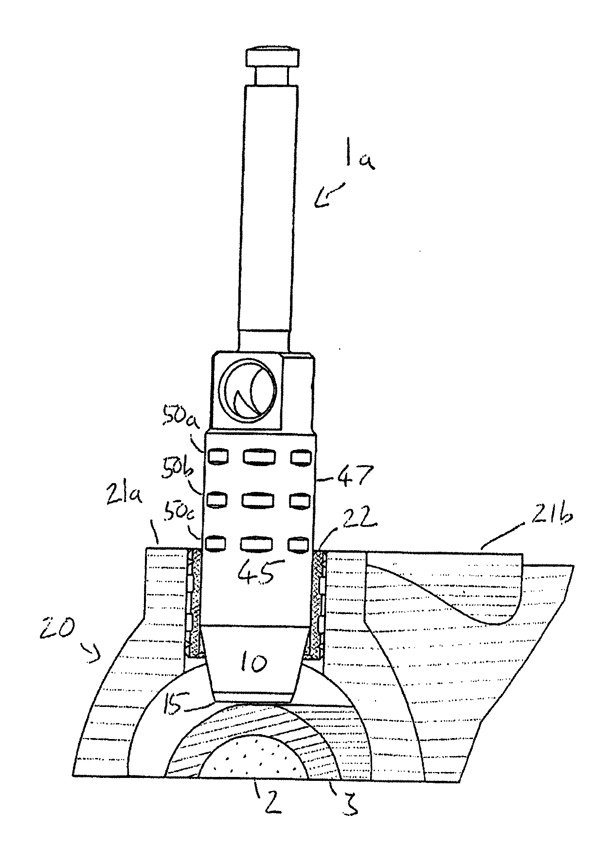
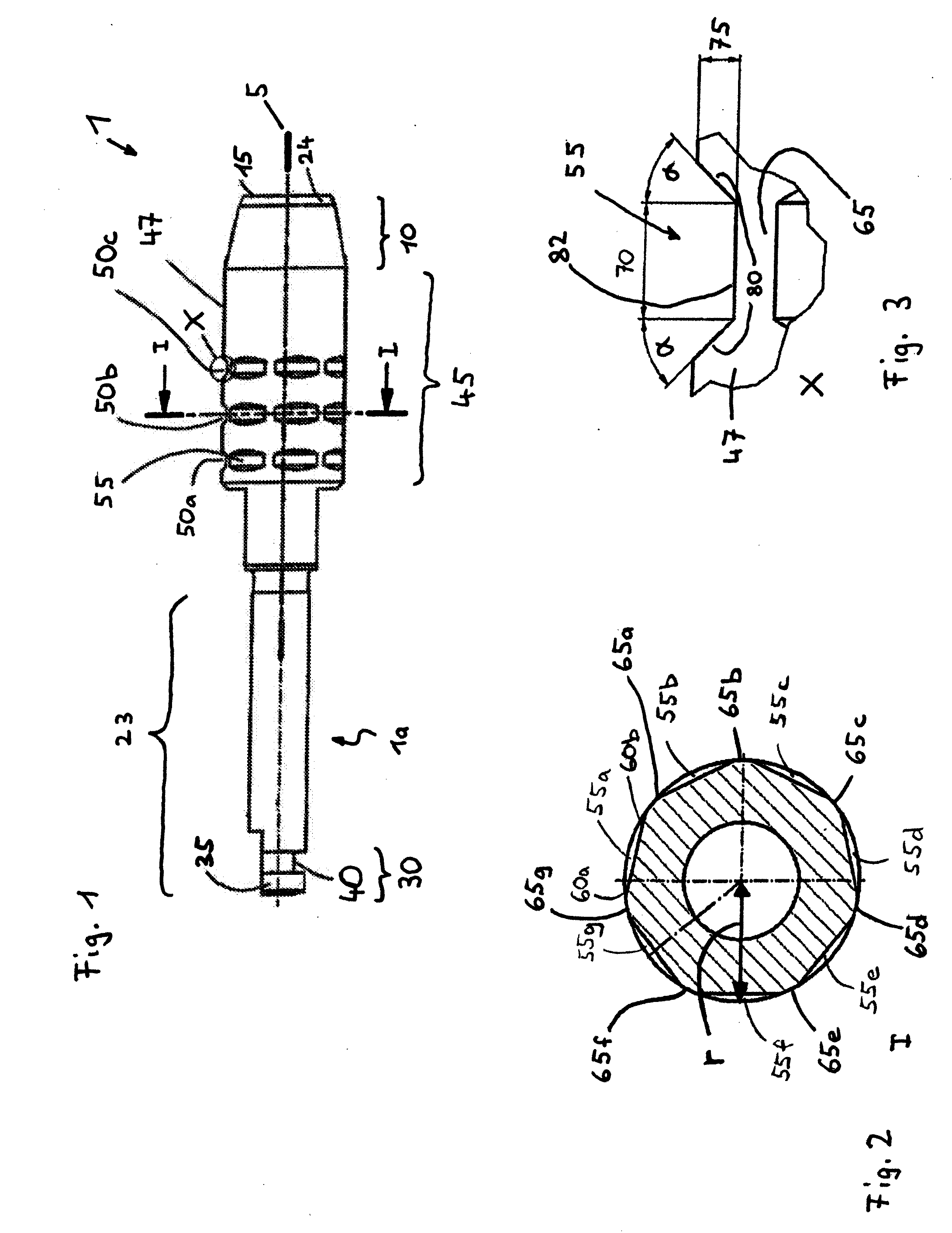
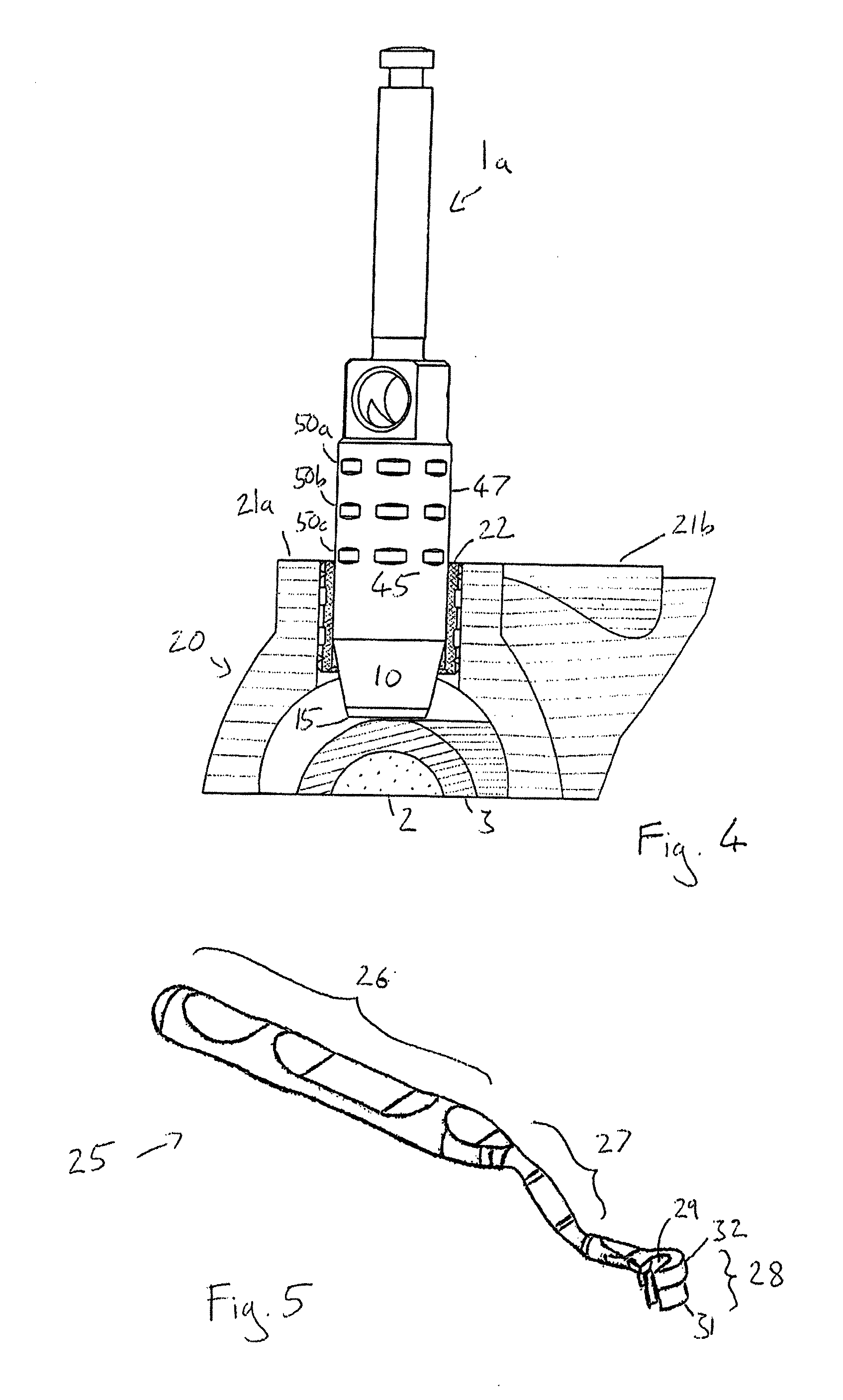
[0051]FIG. 1 shows a first illustrative embodiment of a tool 1 according to the present invention in the form of a mucosa punch 1a. The punch 1a comprises a longitudinal axis 5. The punch 1a has at one end, that is the distal end, a functional element 10 in the form of a truncated hollow cone having a cutting edge 15 at the tip 24. Said cutting edge 15 is intended for cutting the mucosa prior to drilling in the bone tissue. At the opposite end, the punch 1a has a shank part 23 with an exposed connection area 30. The connection area 30 is intended to be received in a generally known drill holder device and has a rotation-preventing means 35, and an axial securing means 40. The rotation-preventing means 35 and the axial securing means 40 allow for the mucosa punch 1a to be brought into a fixed connection with the drill holder device, which, for example, is part of a drill drive or a hand drill.

[0052]The punch 1a comprises a substantially circular cylindrical guide portion 45 with a ra...


PUM


Abstract

Surgical tool for use in guided surgery comprising a distal end portion having a functional element, a shank on the opposite end of the tool, and a substantially circular cylindrical guide portion. The guide portion is located between the functional element and the shank and has at least one visual marker. The at least one marker has at least one recess which is finite in the circumferential direction such that, at the axial location of the recess a section of guide portion having outer radius r is maintained.

Description

FIELD OF THE INVENTION[0001]The present invention relates to a dental surgical tool comprising a guide portion for use in guided surgery.[0002]In order to place a dental implant within the mouth of a patient, a suitable cavity must be created within the patient's jaw bone. This cavity must be of the correct depth and diameter, and be correctly positioned and orientated. This is crucial in order to ensure that the implant does not interfere with existing teeth, nerve bundles and / or implants and also to give good stability and an aligned and aesthetically pleasing end result.BACKGROUND[0003]The availability of computer tomography and specialised computer software allows for detailed pre-operative planning, during which the precise location and dimensions of the required cavity in a patient's jaw bone can be virtually modelled. Based on this model, a template specific to each patient can be designed and manufactured, which can be placed over the patient's teeth, gums or bone. This temp...

Claims


Application Information

Patent Timeline
IPC IPC(8): A61C19/04
CPCA61B19/201A61B2019/462A61C8/0089A61C1/084A61B2019/5437A61B90/11A61B2090/062A61B2090/3937
Inventor SUTER, EDMUNDCOURVOISIER, STEPHANE
Owner STRAUMANN HLDG AG
Learn More