
Two-Stroke Internal Combustion Engine and Its Scavenging Method

a two-stroke, internal combustion engine technology, applied in combustion engines, machines/engines, pistons, etc., can solve the problems of large changes in air-fuel ratio, difficulty in deciding appropriate timing, and regulating the amount of heading air, so as to reduce acceleration failure or engine stop

Inactive Publication Date: 2011-07-28
YAMABIKO CORP
View PDF12 Cites 1 Cited by
  • Summary
  • Abstract
  • Description
  • Claims
  • Application Information

AI Technical Summary

Benefits of technology

[0014]It is therefore an object of the present invention to provide a two-stroke internal combustion engine and a scavenging method thereof that employ a scavenging system using air for scavenging and capable of reducing acceleration failure or engine stop caused by sudden acceleration.
[0015]A further object of the present invention is to provide a two-stroke internal combustion engine and a scavenging method thereof capable of substantially increasing the amount of air usable as heading air for scavenging that uses heading air charged in scavenging passages.
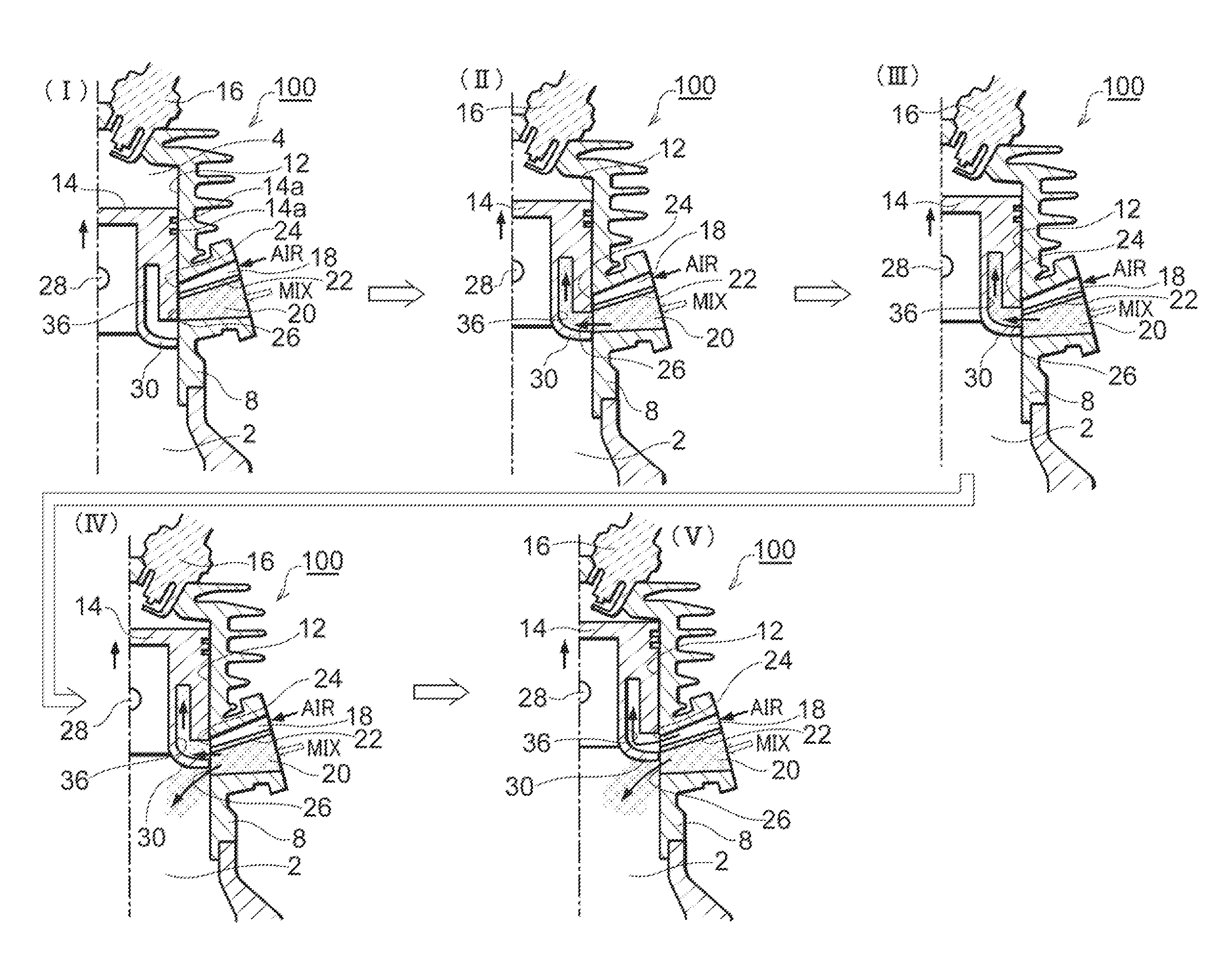
[0020]The term “rich air-fuel mixture” is used in this specification only for distinguishing it from “lean air-fuel mixture”. Thus, the “rich” air-fuel mixture is normal air-fuel mixture of a predetermined air-fuel ratio just generated by a carburetor and delivered to the mixture passage. According to the first aspect of the present invention, the combustion chamber is scavenged by heading air as some conventional methods did. Even if blow-by of air-fuel mixture occurs, the amount of fuel component outflow due to the blow-by can be reduced because it is the lean air-fuel mixture that enters next to the air when they are introduced into the combustion chamber. The lean air-fuel mixture contains only a small amount of fuel. Therefore, it is not only possible to reduce blow-by of air-fuel mixture by scavenging primarily using the air, but also possible to minimize acceleration failure or engine stop upon sudden acceleration, which are problems involved in conventional air-headed scavenging, by introducing the lean air-fuel mixture next to the air into the combustion chamber.
[0025]According to the second aspect of the present invention, it is possible to minimize acceleration failure or engine stop caused by sudden acceleration while reducing blow-by of air-fuel mixture here again like the first aspect of the invention. In parallel, according too the second aspect of the invention, it is possible to prevent the air from directly hitting a residual of the rich air-fuel mixture in the crankcase or in the scavenging passage. This is because the lean air-fuel mixture in an amount regulated at least by a crank angle is charged in the scavenging passage before the air is charged. As to the lean air-fuel mixture, the amount regulated by the crank angle means an amount intended by the engine design. As a result, the lean air-fuel mixture exists as a buffer between the air and the rich air-fuel mixture when the air is charged in the scavenging passage. Thus, this scavenging method prevents that a considerable amount of air charged in the scavenging passage mixes with rich air-fuel mixture and thereby changes to a lean air-fuel mixture, and therefore ensures that almost all of the substantially increased amount of air acts to scavenge the combustion chamber.
[0026]Furthermore, according to the second aspect of the invention, since the lean air-fuel mixture is charged in the scavenging passage before the air is charged therein, it is possible to prevent the air from entering the crankcase through the scavenging passage. Consequently, the air-fuel mixture in the crankcase can be prevented to fluctuate in air-fuel ratio due to undesirable intrusion of the air for scavenging into the crankcase. This mechanism is explained below in greater detail. When the piston starts its upstroke, negative pressure in the crankcase increases, and this may cause the air charged in the scavenging passage to enter the crankcase. According to the present invention, however, the lean air-fuel mixture is charged in the scavenging passage with before the air is supplied therein. Therefore, even though some gas inevitably intrudes into the crankcase from the scavenging passage, the gas that may intrude is the lean air-fuel mixture instead of air. Thus, the use of the lean air-fuel mixture as a buffer between the rich air-fuel mixture and the air also contributes to reducing fluctuations of the air-fuel ratio of the air-fuel mixture in the crankcase and hence contributes to stabilizing the engine operation.

Problems solved by technology

Actually, however, there is the problem of “blow-by”, which is the phenomenon that air-fuel mixture partly flows out of the engine.
The scavenging methods as disclosed in Patent Document 2 and Patent Document 3 utilize the heading or leading air, but these methods have difficulties in deciding appropriate timing to start scavenging with the heading air and in regulating the amount of the heading air.
Furthermore, these scavenging methods using heading air are liable to suffer large changes in air-fuel ratio in the combustion chamber upon sudden acceleration, which often results in acceleration failure or engine stop.
This means that the fuel component contained in the two parts of the heading air is undesirably emitted by scavenging.

Method used


Image

  • Two-Stroke Internal Combustion Engine and Its Scavenging Method
  • Two-Stroke Internal Combustion Engine and Its Scavenging Method
  • Two-Stroke Internal Combustion Engine and Its Scavenging Method

Examples


Embodiment Construction

[0041]A preferred embodiment of the present invention is explained below with reference to the accompanying drawings.

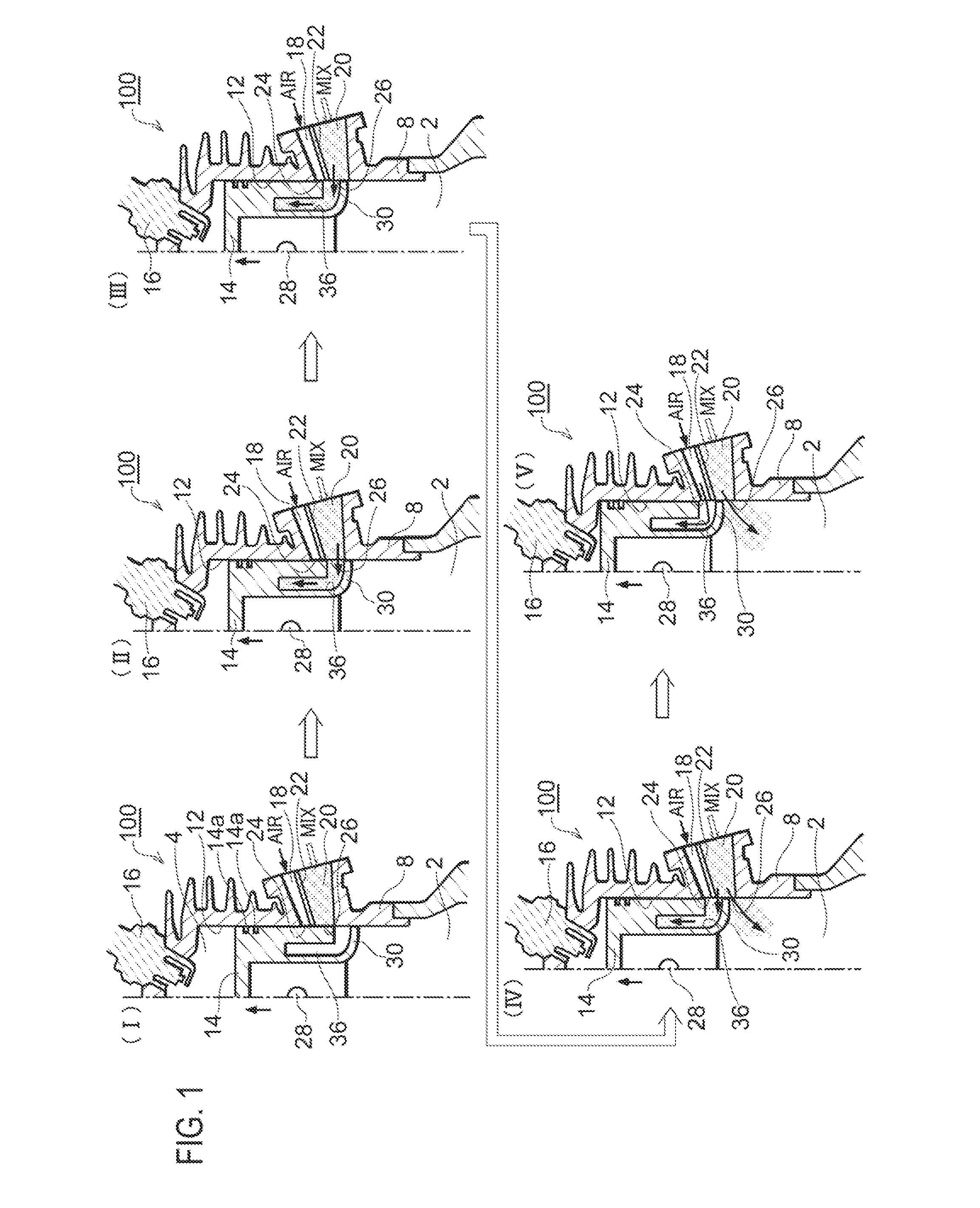
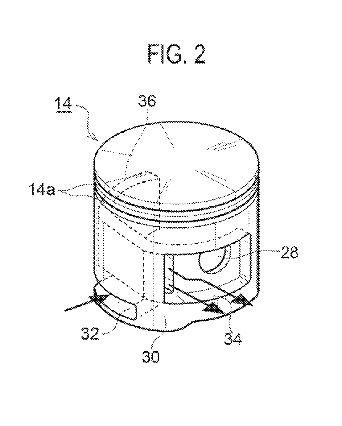
[0042]As illustrated in FIG. 1 and FIG. 4, an air-cooled two-stroke internal combustion engine 100 according to an embodiment of the invention is a single-cylinder, compact-sized engine to be mounted in, for example, a hand-held work apparatus such as a chain saw or a brush cutter. Like conventional ones, this engine 100 includes scavenging passages 6 each communicating with both a crankcase 2 and a combustion chamber 4 (FIG. 4). The scavenging passages 6 are formed as an integral part of a cylinder block 8. The cylinder bore 12 has formed scavenging windows 10 each being an exit end of each scavenging passage 6. The scavenging windows 10 are opened and closed by reciprocal movements of the piston 14.

[0043]Like conventional ones, the engine 100 supplies air-fuel mixture (rich air-fuel mixture in the aforementioned context of this specification) into the crankcase 2, t...


PUM


Abstract

In a two-stroke internal combustion engine using air for scavenging its combustion chamber (4), a scavenging passage (6) communicating with a crankcase (2) and a combustion chamber (4) is charged first with rich air-fuel mixture generated by a carburetor, next with lean air-fuel mixture, and next with air through an in-piston passage (36). The lean air-fuel mixture is generated in the in-piston passage 36 by diluting the air-fuel mixture with the air. In each scavenging stroke to scavenge the combustion chamber (4), the combustion chamber (4) is supplied first with the air (40) and next with the lean air-fuel mixture (42) from the scavenging passage (6). The use of the lean-air-fuel mixture (42) next to the air (40) contributes to reduce acceleration failure or engine stop caused by sudden acceleration.

Description

CROSS-REFERENCE TO RELATED APPLICATIONS[0001]The present application claims priority from Japanese Patent Application No. 2010-12551, filed Jan. 22, 2010, which is incorporated herein by reference.FIELD OF THE INVENTION[0002]The present invention relates to a two-stroke internal combustion engine configured to use air-fuel mixture compressed in its crankcase for scavenging the crankcase. The invention also relates to a scavenging method for the engine.BACKGROUND OF THE INVENTION[0003]Two-stroke internal combustion engines are widely used in work apparatuses such as chain saws and brush cutters. This kind of portable power tools or work apparatuses, in general, have mounted an engine of a crankcase compression type that introduces air-fuel mixture into the crankcase and compresses it therein with a piston.[0004]As already known, two-stroke internal combustion engines use air-fuel mixture to scavenge their combustion chambers. It is ideal that scavenging can be completed without any o...

Claims


Application Information

Patent Timeline
IPC IPC(8): F02B33/04
CPCF02B25/14F02F3/24F02B2075/025F02B25/22
Inventor KAWAMURA, KUNIMUNE
Owner YAMABIKO CORP
Learn More