Tether energy supply system

a technology of energy supply system and tether, which is applied in the direction of tethered aircraft, power plant fuel tanks, transportation and packaging, etc., can solve the problems of increasing the weight of the uav, limiting the flight time limiting the fuel capacity of the conventional uav, so as to eliminate the uav weight associated either, eliminate the risk, and eliminate the disruption

Inactive Publication Date: 2011-07-28
HONEYWELL INT INC
View PDF70 Cites 83 Cited by
  • Summary
  • Abstract
  • Description
  • Claims
  • Application Information

AI Technical Summary

Benefits of technology

[0004]The discovery presented herein outlines a tether continuous energy supply system for an unmanned aerial vehicle (UAV) that has the surprising beneficial effects of (1) eliminating UAV weight associated either with fuel or with a voltage reducing transformer and a cooling apparat

Problems solved by technology

However, fuel capacity limits flight time for conventional UAVs.
In addition, carrying fuel onboard greatly increases the UAV's weight.
UAVs that instead receive electrical power via a tether must carry onboard a voltage reducing transformer, again adding to the weight of the UAV.
Also, the heat producing components on tethered electrically powered UAVs often require a coo

Method used


Image

  • Tether energy supply system
  • Tether energy supply system
  • Tether energy supply system

Examples


Embodiment Construction

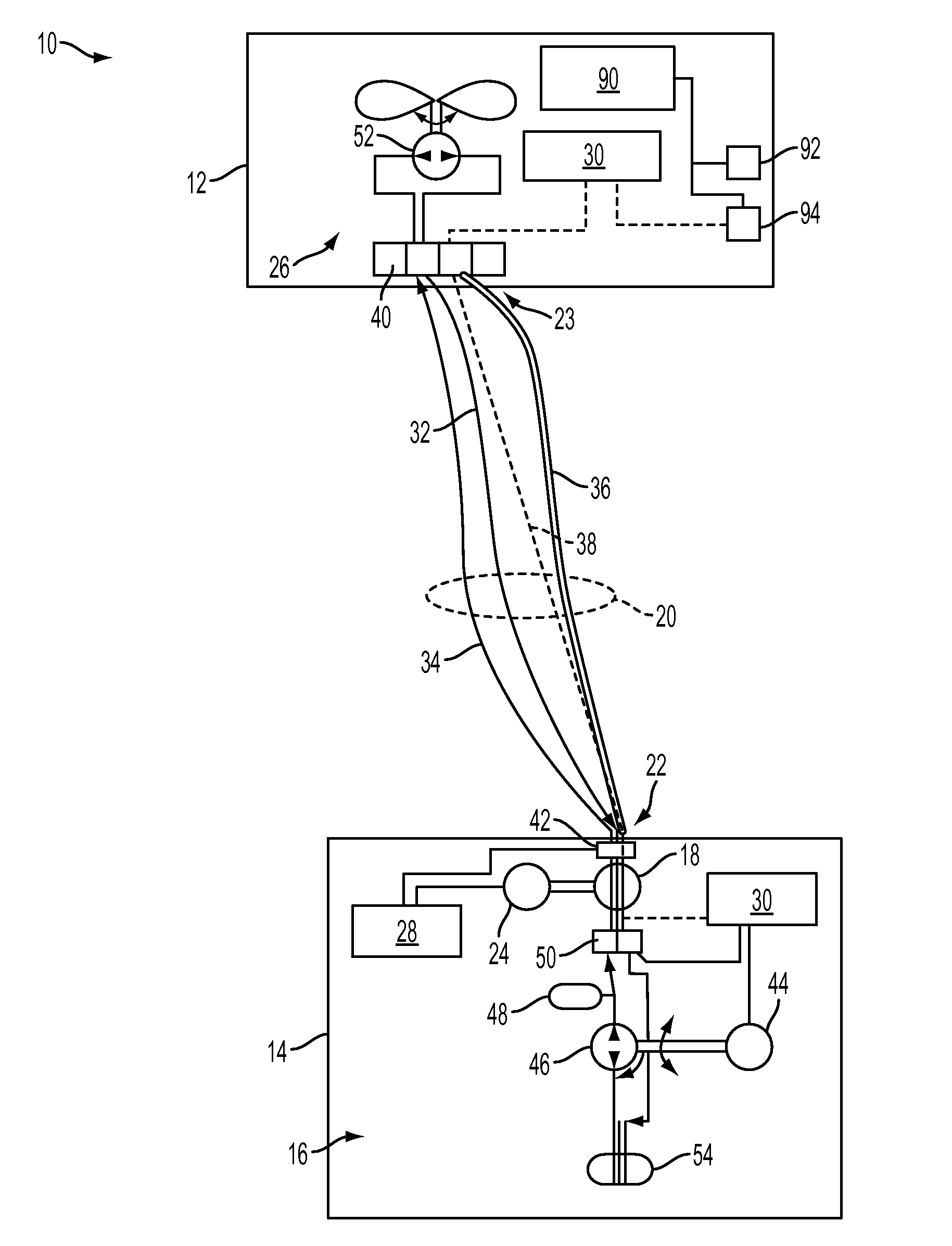
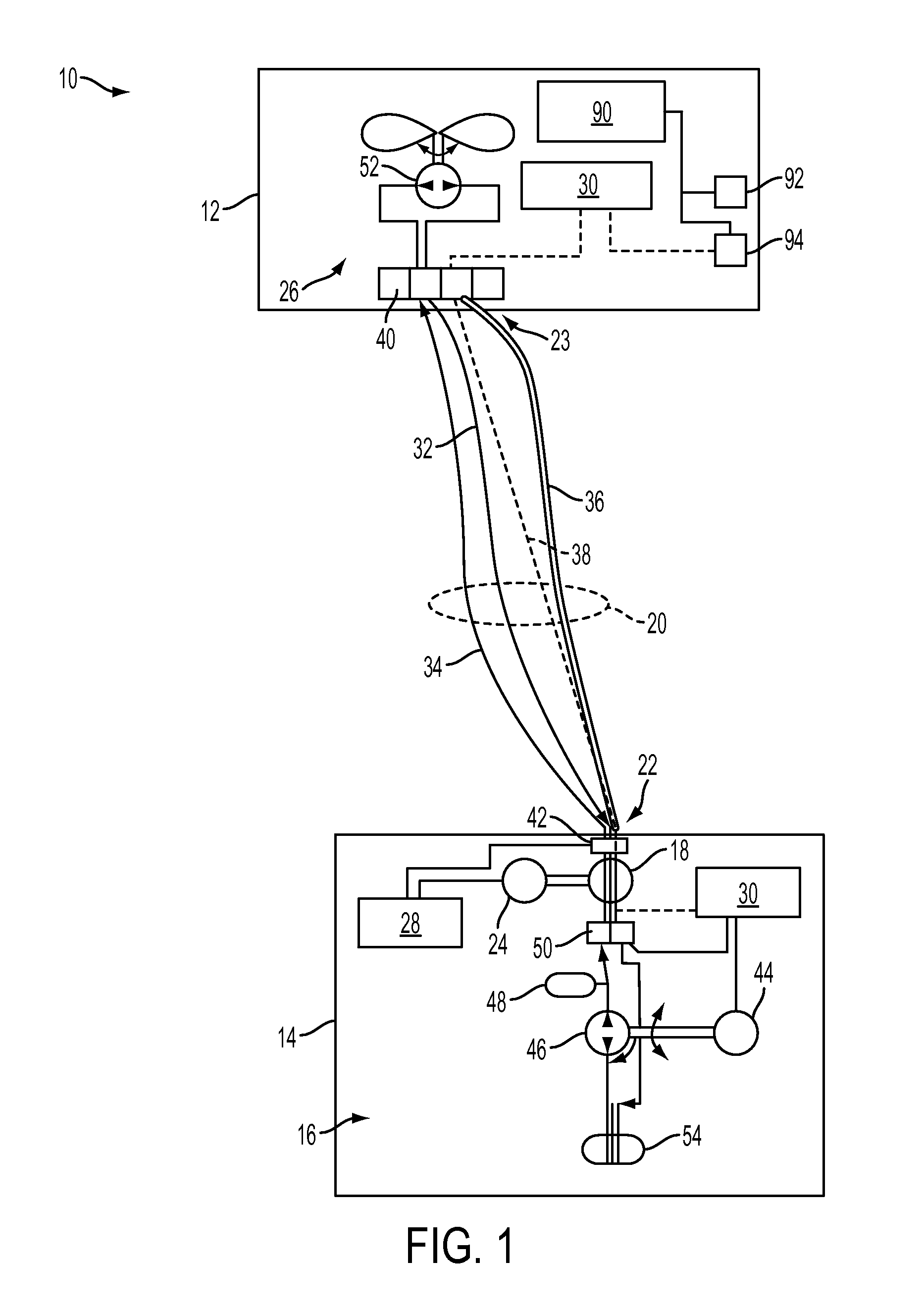
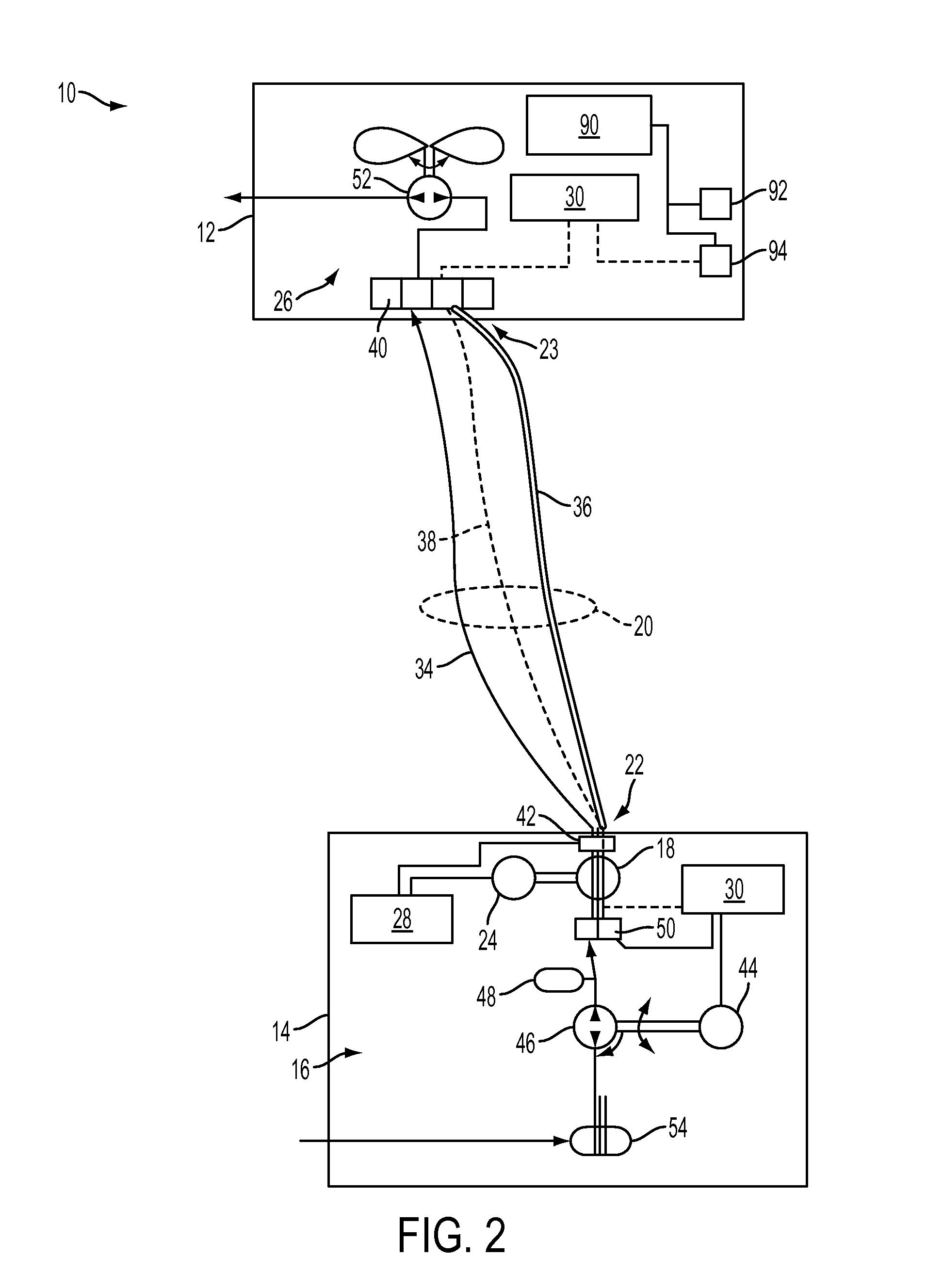
[0012]In a first aspect, the present invention provides a tether continuous energy supply system 10 for an unmanned aerial vehicle 12 comprising: (a) a ground station 14, (b) a ground station energy system 16, (c) a spool 18 coupled to the ground station energy system 16 at a rotating joint, (d) a tether 20 that is wound about the spool 18, wherein a first end 22 of the tether 20 is coupled to the rotating joint, (e) a tension control motor 24 coupled to both the spool 18 and the ground station energy system 16, (f) an unmanned aerial vehicle 12 coupled to a second end 23 of the tether 20, (g) a UAV energy system 26, (h) a fluid that moves throughout the tether continuous energy supply system 10, (i) a tension control system 28 that receives and transmits signals from a plurality of sensors contained within the tether continuous energy supply system 10, and (j) a distributed controls system 30 that receives and transmits signals from the plurality of sensors contained within the tet...


PUM


Abstract

A tether continuous energy supply system for an unmanned aerial vehicle comprising: a ground station, a ground station energy system, a spool coupled to the ground station energy system at a rotating joint, a tether that is wound about the spool, wherein a first end of the tether is coupled to the rotating joint, a tension control motor coupled to both the spool and the ground station energy system, an unmanned aerial vehicle coupled to a second end of the tether, a UAV energy system, a fluid that moves throughout the tether continuous energy supply system, a tension control system that receives and transmits signals from a plurality of sensors contained within the tether continuous energy supply system, and a distributed controls system that receives and transmits signals from the plurality of sensors contained within the tether continuous energy supply system.

Description

BACKGROUND OF THE INVENTION[0001]Remotely controlled aerial observational and broadcasting platforms and unmanned aerial vehicles (UAVs) are known to provide video and infrared observation and surveillance of persons, industrial equipment, and security environments. UAVs are sometimes used by military and governmental agencies to survey territories by air. However, fuel capacity limits flight time for conventional UAVs. In addition, carrying fuel onboard greatly increases the UAV's weight. UAVs that instead receive electrical power via a tether must carry onboard a voltage reducing transformer, again adding to the weight of the UAV. Also, the heat producing components on tethered electrically powered UAVs often require a cooling apparatus to prevent overheating, likewise adding to the weight of the UAV.[0002]UAVs typically rely on wireless radio communication technologies for command, control, and data transmission. However, radio communications are susceptible to intentional and un...

Claims


Application Information

Patent Timeline
IPC IPC(8): B64D37/00B65H75/48
CPCB64C39/022B64C2201/148B64C39/024B64U2201/202B64U10/60
Inventor O'BRIEN, PATRICKGOOSSEN, EMRAY R.MARTINEZ, STEVEN D.
Owner HONEYWELL INT INC
Why Eureka
Try Eureka