Solar cell power supply device and rechargeable battery solar charging method

a solar charging and solar cell technology, applied in the direction of electrochemical generators, secondary cell servicing/maintenance, transportation and packaging, etc., can solve the problems of difficult to accurately charge rechargeable batteries into the fully-charged state, difficult for solar batteries to constantly generate stable electric power, and large variation with each passing minute, etc., to eliminate or reduce improper detection of the fully-charged state, the effect of efficient discharg

Inactive Publication Date: 2011-07-28
SANYO ELECTRIC CO LTD
View PDF6 Cites 42 Cited by
  • Summary
  • Abstract
  • Description
  • Claims
  • Application Information

AI Technical Summary

Benefits of technology

[0022]In a solar battery power supply device according to a thirteenth aspect of the present invention, a charging operation available temperature range of the battery cell is set into a range different from a discharging operation available temperature range. The discharging operation available temperature range extends on the low temperature side relative to the charging operation available temperature range. According to this construction, it is possible to efficiently discharge also during the nighttime in which the battery cell temperature generally becomes lower as compared with the battery cell temperature when the battery cell is charged in the daytime.
[0023]A rechargeable battery solar charging method according to a fourteenth aspect of the present invention is a method for supplying charging current to a battery pack that includes a plurality of rechargeable battery cells connected to each other in series or in parallel by using electric power generated by a solar panel that inc

Problems solved by technology

In this type of electric power system, the rechargeable battery is charged not with stable power source such as usual commercial power the output of which is stable, but with unstable electric power the output of which substantially varies in accordance with sunlight power.
It is difficult for solar batteries to constantly generate stable electric power.
In particular, the variation with each passing minute is very large.
For this reason, it is not easy to charge rechargeable batteries accurately into the fully-charged state by using solar batteries, which are an unstable electric power source.
Also, it is difficult to determine the charging current cutting-off timing.
However, the charging current obtained by solar batteries substantially varies with each passing minute.
Acc

Method used


Image

  • Solar cell power supply device and rechargeable battery solar charging method
  • Solar cell power supply device and rechargeable battery solar charging method
  • Solar cell power supply device and rechargeable battery solar charging method

Examples


embodiment 1

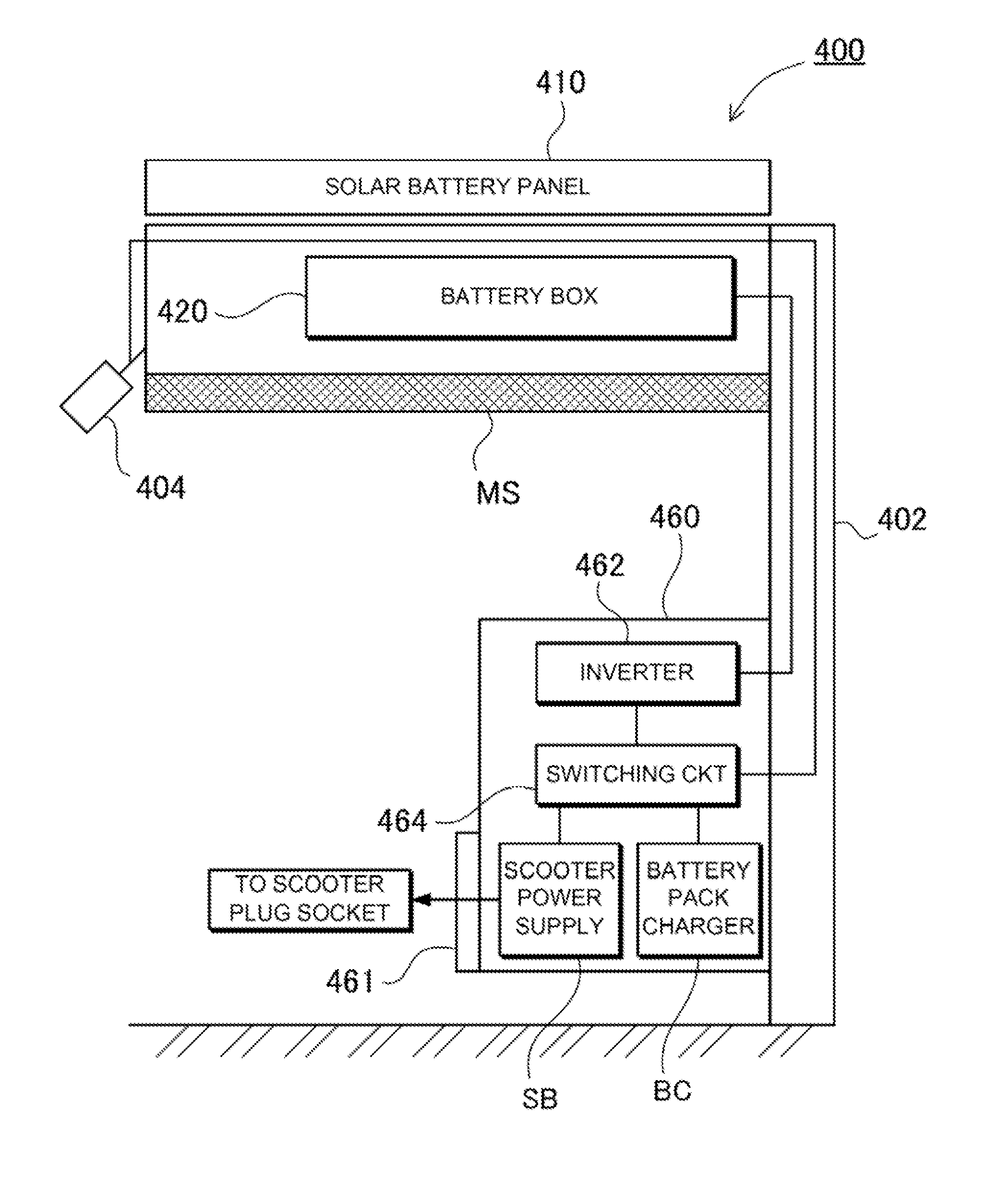
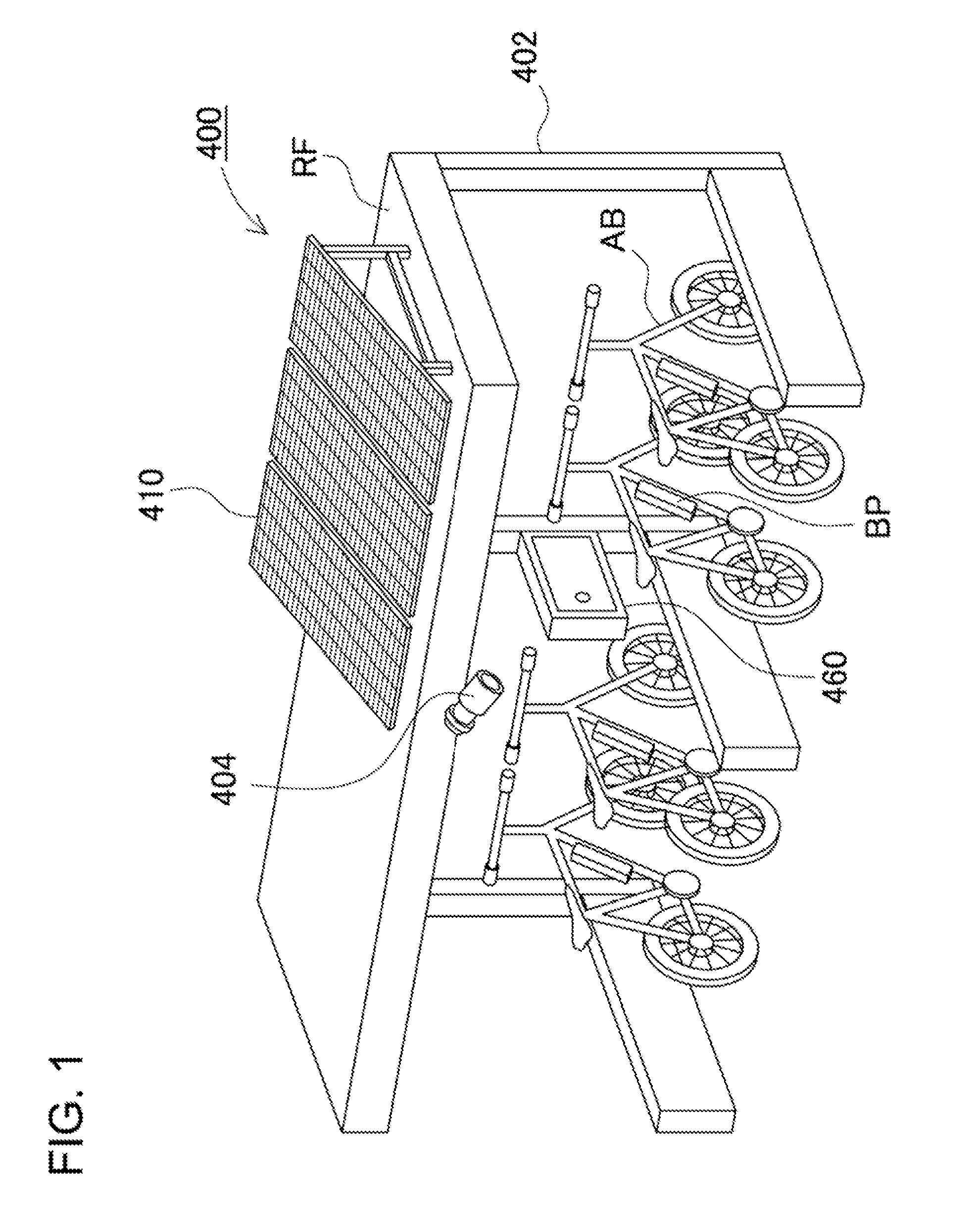
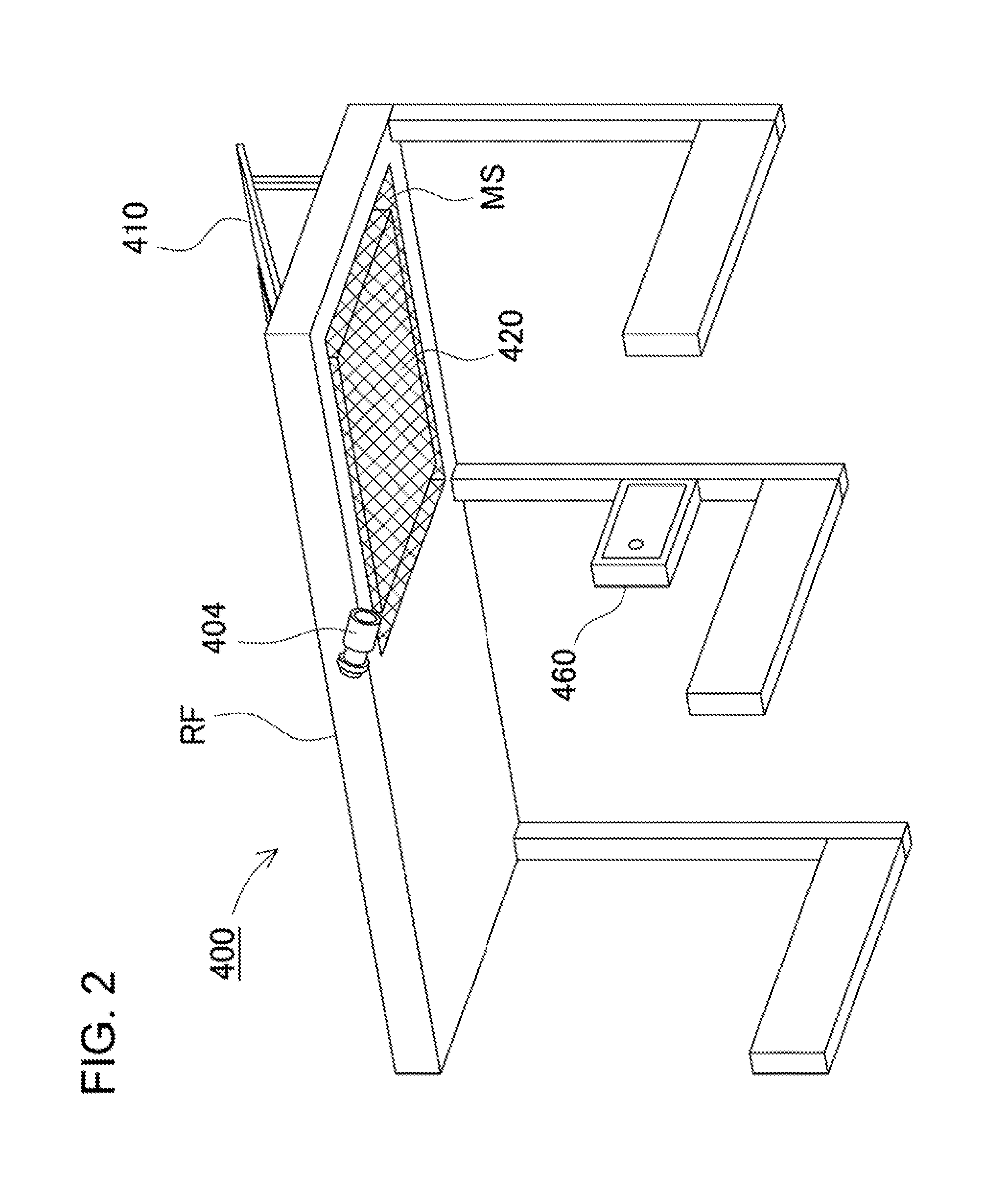
[0061]A solar battery power supply device 400 according to an embodiment 1 of the present invention will be described with reference to FIGS. 1 to 20. FIG. 1 is a schematic view illustratively showing the solar battery power supply device applied to charging equipment in a bike shed. FIG. 2 is a schematic view showing a roof of the bike shed as viewed from the lower side. FIG. 3 is a block diagram showing the construction of the solar battery power supply device shown in FIG. 1. FIG. 4 is a schematic view showing the front of a console. FIG. 5 is a perspective view showing the outward appearance of a battery box as viewed from the upper side. FIG. 6 is a perspective view showing the battery box shown in FIG. 5 as viewed from the lower surface side. FIG. 7 is an exploded perspective view showing the battery box shown in FIG. 5 with an upper case being removed. FIG. 8 is a cross-sectional view of the battery box shown in FIG. 5 taken along the line VIII-VIII. FIG. 9 is an exploded per...

embodiment 2

[0118]Although the solar battery power supply device 400 has illustratively been described that adds battery pack charging function to the bike shed in the foregoing embodiment 1, the load to be connected to the solar battery power supply device is not limited to this. Various types of electric devices can be connected to the solar battery power supply device. The following description will describe a solar battery power supply device 100 according to an embodiment 2 that drives a street light as load with reference to FIGS. 21 to 31. FIG. 21 is a perspective view showing the outward appearance of the solar battery power supply device as viewed from the front side. FIG. 22 is a perspective view showing the outward appearance of the solar battery power supply device as viewed from the front side. FIG. 23 is a perspective view showing the solar battery power supply device shown in FIG. 22 with a battery cover being removed whereby exposing a battery box. FIG. 24 is a perspective view ...


PUM


Abstract

A charging operation controlling portion controls charging current or charging voltage when the battery pack 440 is charged with electric power generated by the solar panel 410. The current detecting portion 456 detects charging current of the battery pack. The voltage detecting portion 455 detects battery voltage of the battery pack. The charging operation controlling portion, when the battery pack 440 is brought close to the fully-charged state, cuts off the charging current at predetermined timing for a charging operation stop period, and compares the battery voltage of the battery pack 440 with a predetermined voltage value as a restart voltage value in the charging operation stop period. The charging operation controlling portion determines that the battery pack 440 is fully charged if the battery voltage of the battery pack 440 is not less than the predetermined voltage value as the restart voltage value, and cuts off the charging current.

Description

BACKGROUND OF THE INVENTION[0001]1. Field of the Invention[0002]The present invention relates to a solar cell power supply device that generates electric power by sunlight and charges a rechargeable battery with the generated electric power and a method for charging the rechargeable battery by using the solar battery, and in particular to a solar cell power supply device that includes a solar battery and a rechargeable battery directly connected to each other without a DC / DC converter connected between them but can stably charge the rechargeable battery by using the solar battery and a method for charging the rechargeable battery by using the solar battery.[0003]2. Description of the Related Art[0004]In terms of environmental issues such as CO2 reduction, an electric power system has been proposed that stores electric power generated without using fossil fuels by using natural energy sources and uses the stored electric power (for example, see Japanese Patent Laid-Open Publication N...

Claims


Application Information

Patent Timeline
IPC IPC(8): H01M10/46
CPCH02J7/0027H02J7/008H02J7/045H02J7/35Y02T10/7088Y02E10/566B60L2230/22Y02T90/12H02J7/355B60L53/51Y02T10/7072Y02T10/70H02J7/04H02J7/0045H02J7/0014H02J7/007182H02J2310/48Y02E10/56
Inventor MINO, TAKAYUKIMORINA, KENICHIKURIHARA, TOSHITAKE
Owner SANYO ELECTRIC CO LTD
Why Eureka
Try Eureka