Sample storage

a sample and storage technology, applied in the field of sample storage, can solve the problems of increasing the possibility of false recognition due to the superimposed sample contained in the sample storage, the increase of the possibility of false recognition by the recognition system, such as the scanner, and the increase of the risk of false recognition

Active Publication Date: 2011-07-28
NAKAHANA YOKO +1
View PDF2 Cites 17 Cited by
  • Summary
  • Abstract
  • Description
  • Claims
  • Application Information

AI Technical Summary

Benefits of technology

[0027]A sample storage according to the present invention enables barcodes or two-dimensional codes on the outer surface thereof to be written directly to an opaque writable outer element, and the barcodes or two-dime...

Problems solved by technology

There is a risk of false recognition due to superimposing of a barcode or two-dimensional code on the outer surface of the sample storage and a sample contained in the sample storage.
The possibility of false recognition due to the superimposing on a sample contained in the sample storage may increase, especially when a bar code is present in a large form on the side surface.
Especially when the sample is not transparent liquid, and the color tone of the sample is deep or turbid, the possibility of false recognition...

Method used


Image

  • Sample storage
  • Sample storage
  • Sample storage

Examples


embodiment 1

[0041]A sample storage 100 in embodiment 1 according to the present invention is described.

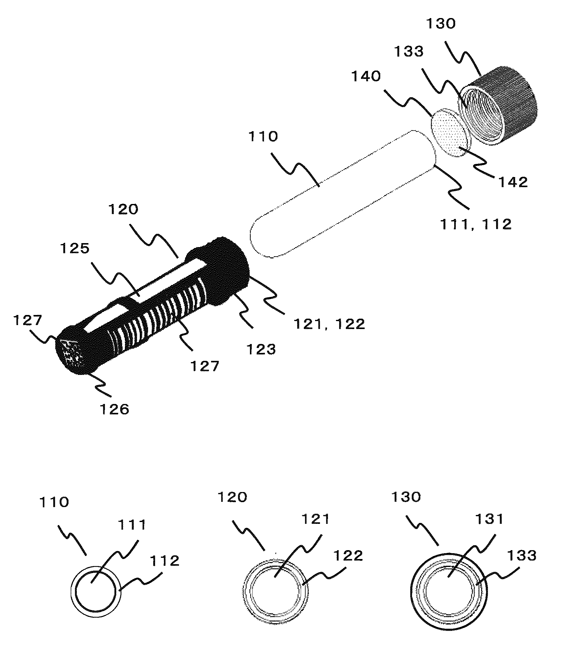
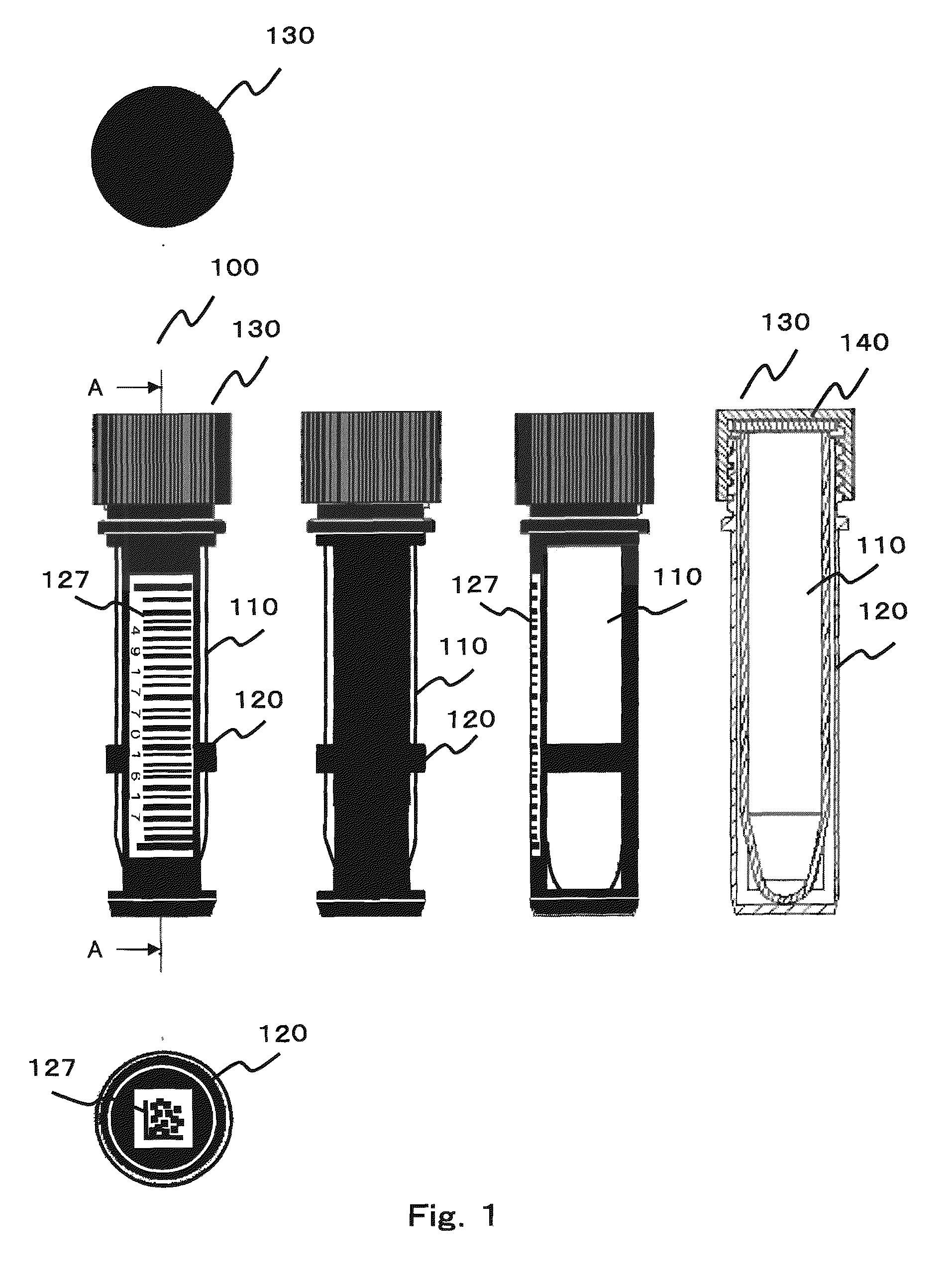
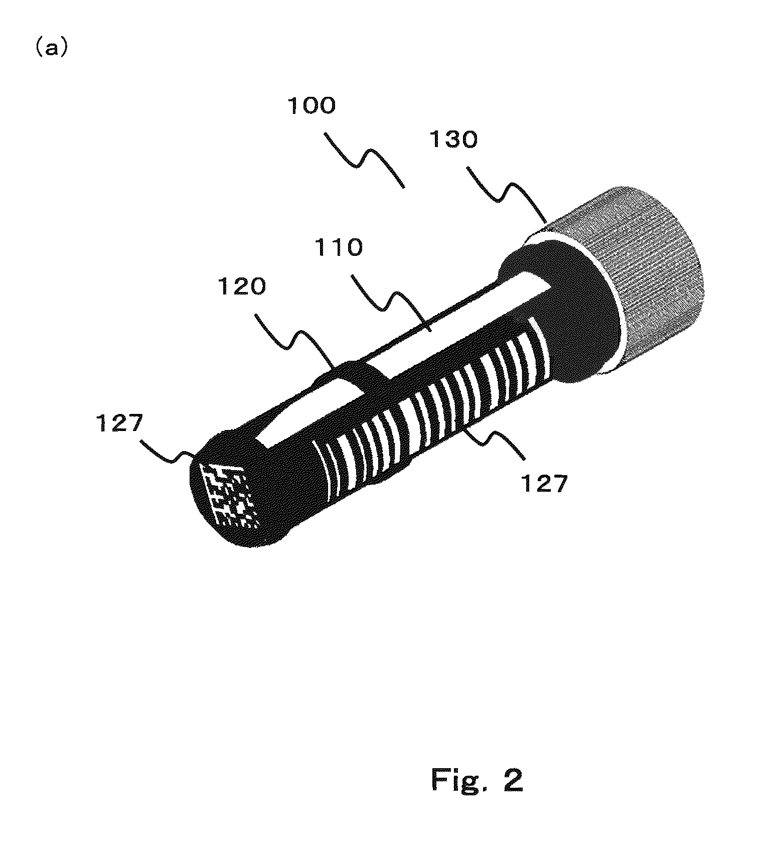
[0042]FIG. 1 is a schematic view of a sample storage 100 in embodiment 1 according to the present invention. A front view, right side view, back view, top view, bottom view, and A-A cross-sectional view are shown. FIG. 2 is a perspective view, and FIG. 3 is an exploded view of a sample storage 100, which explodes into individual components.

[0043]As shown in FIG. 1 through FIG. 3, a sample storage 100 in embodiment 1 comprises a storage tube 110, an opaque writable outer element 120, a lid element 130, and a gasket 140.

[0044]While the material color of opaque writable outer element 120 is black as shown in FIG. 1, but in some other figures, the black coloring of the opaque writable outer element 120 is omitted for the purpose of better visualization and explanation of other aspects. In addition, the coded information 127, one-dimensional barcodes or two-dimensional dot codes, comprises black ba...

embodiment 2

[0074]FIG. 9 is a perspective view of the sample storage 100a in embodiment 2. In this embodiment, a blade is formed at four corners on the bottom of the opaque writable outer element 120, and a female shaped locking mechanism 160b is formed inside the base of each blade. The opaque writable outer element 120 comprises a white polypropylene molded part that forms a square tubular shape, having a large opening 125.

[0075]While the storage tube 110 forms a tubular shape with a cup-shaped bottom, a male shaped locking mechanism 160a with a so-called “barb” is provided annularly outside the bottom.

[0076]A lid element 130 comprises an opaque white polyethylene molded part. Samples can be sealed properly according to the property of the sample stored in the storage tube 110, for example, by using melamine resin or other materials having equivalent hardness, such as phenol resin, for lid element 130, and by intervening a silicon or fluorine-based resin gasket between the top flat surface of...

embodiment 3

[0079]FIG. 10 is a perspective view of a sample storage 100b in embodiment 3.

[0080]The storage tube 110, a transparent hard glass Sptizy-type sample storage, forms a tubular shape with a cup-shaped bottom.

[0081]The opaque writable outer element 120 comprises a white polypropylene molded part that forms a square tubular shape bottom. The locking mechanism 160 forms is defined by the mechanism as described hereinbelow.

[0082]The lid element 130 may be the same element as shown in embodiment 2.

[0083]FIG. 11 is a schematic view of the locking mechanism 160 that fixes the storage tube 110 to the opaque writable outer element 120 in embodiment 3. In this embodiment, the locking mechanism 160b is provided on the inner wall of the opaque writable outer element 120, which forms a tubular shape being slightly reduced toward the bottom. Spiral grooves similar to the inner surface of nuts, having a large number of parallel concavo-convex shapes, are provided on the inner wall other than window a...


PUM


Abstract

Provide a sample storage, in which barcodes and two-dimensional codes printed on the outer surface of the sample storage can be read correctly without false recognition. A storage tube 110 is made of transparent material, comprising a top opening. An opaque writable outer element 120 is installed outside by covering storage tube 110 throughout from the bottom surface to the side surface. An opaque writable outer element 120 is to be used as a medium on which coded information that can be read by optical lv reading is written. The opaque writable outer element 120 is pushed in and irreversibly fixed to the storage tube 110 by a locking mechanism. At least one window 125 is provided, which enables a sample 200 contained to be observed, with the opaque writable outer element 120 installed outside. Accordingly, it enables coded information written on the opaque writable outer element 120 to be read, and sample 200 contained to be observed through the window 125.

Description

TECHNICAL FIELD[0001]This invention relates to a sample storage that is used for storing a large number of samples, and applicable to various uses in storing samples. For example, it is used in enclosing and storing developing medicine samples. Also, it is used for storing samples that hold gene information of DNA in the medical field.BACKGROUND ART[0002]In the research and development of medicine and chemicals, storage tubes are used extensively in storing a large number of samples. For example, scientists prepare a large number of samples for a comparative experiment with slightly changing conditions such as blending amount, and they use storage tubes for storing the samples for a required period of time while handling them.[0003]In order to control and store a large number of storage tubes at a time as described above, it is necessary to identify each storage tube. In the past they were identified by handwriting a sample name or identification number directly on the outer surface...

Claims


Application Information

Patent Timeline
IPC IPC(8): G01N21/15
CPCB01L3/5082B01L3/5453B01L9/06G01N35/00732B01L2300/022B01L2300/024B01L2300/042B01L2300/021
Inventor NAKAHANA, YOKOKAKUDA, SHINICHIRO
Owner NAKAHANA YOKO
Why Eureka
Try Eureka