
Wireless base station apparatus and wireless communication method

Inactive Publication Date: 2011-07-28
KDDI CORP
View PDF7 Cites 16 Cited by
  • Summary
  • Abstract
  • Description
  • Claims
  • Application Information

AI Technical Summary

Benefits of technology

[0019]In light of the above circumstances, an object of the present invention is to provide a wireless base station apparatus for IDMA communication, by which even when the electric power of the signal received from a terminal device belonging to an adjacent cell decreases, a desired reliability of the generated interference replica signal is obtained, and degradation in the quality of the signal received from a terminal device belonging to the present cell can be prevented.
[0037]In accordance with the present invention, even when the electric power of the signal received from a terminal device belonging to an adjacent cell decreases, a desired reliability of the generated interference replica signal can be secured, thereby improving the reception quality.

Problems solved by technology

In addition, since no spreading process is performed in each terminal device during transmission, it is necessary for a wireless base station apparatus to perform chip-level multiuser interference cancellation.
However, in the wireless base station apparatus 9 in FIG. 5, when electric power of the received signal form a terminal device belonging to another adjacent cell decreases due to attenuation through the relevant channel, a desired likelihood may not be obtained by the error correction through the repetition of the decoding process.
. . , and 942-N have low accuracy and thus low reliability, which causes a decrease in the convergence speed for the iterative operation, and also causes degradation for the convergent point of the bit error rate.

Method used


Image

  • Wireless base station apparatus and wireless communication method
  • Wireless base station apparatus and wireless communication method
  • Wireless base station apparatus and wireless communication method

Examples


Embodiment Construction

[0043]Hereinafter, an embodiment of the wireless base station apparatus and the wireless communication method in accordance with the present invention will be described with reference to the appended figures.

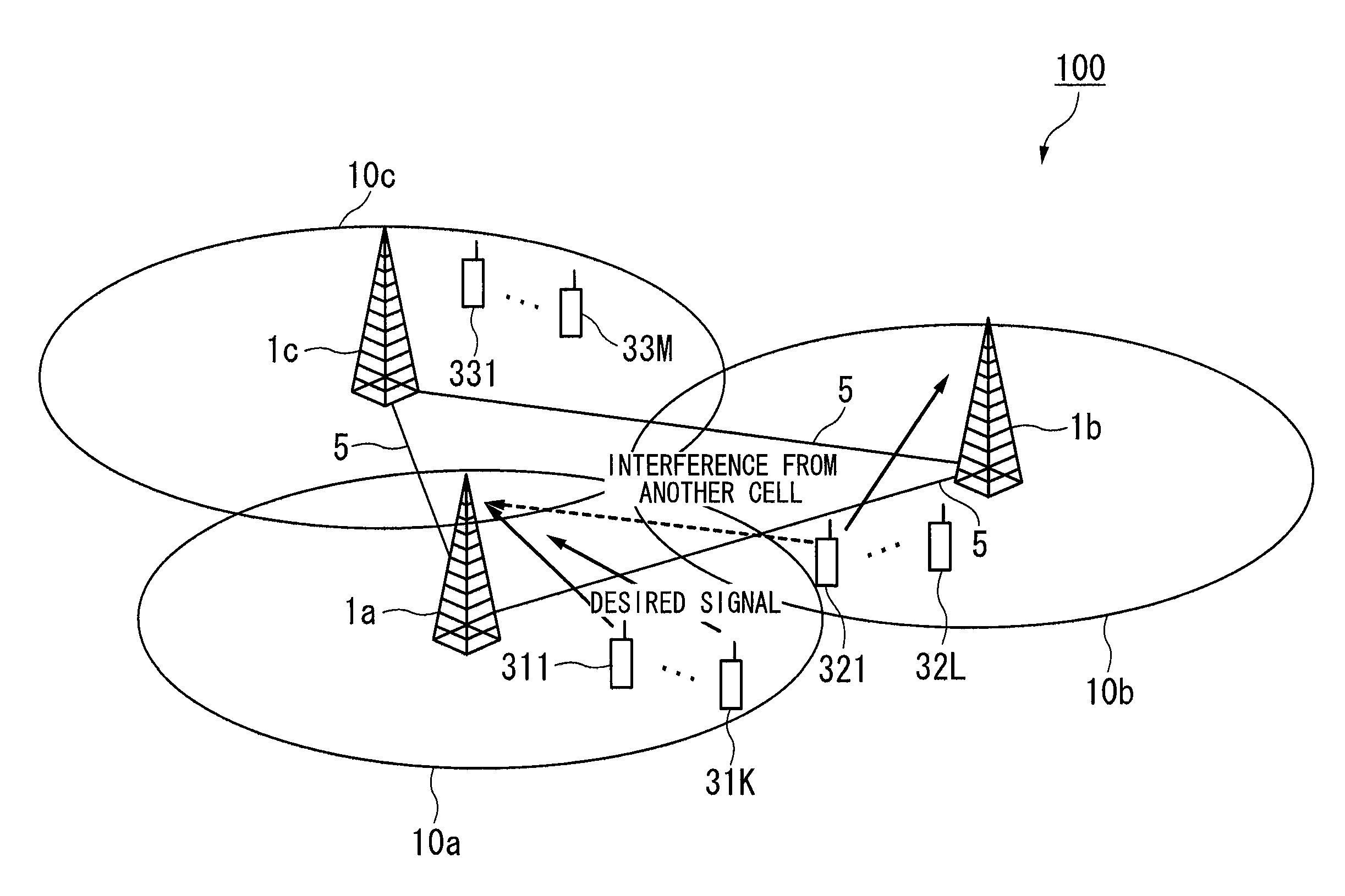
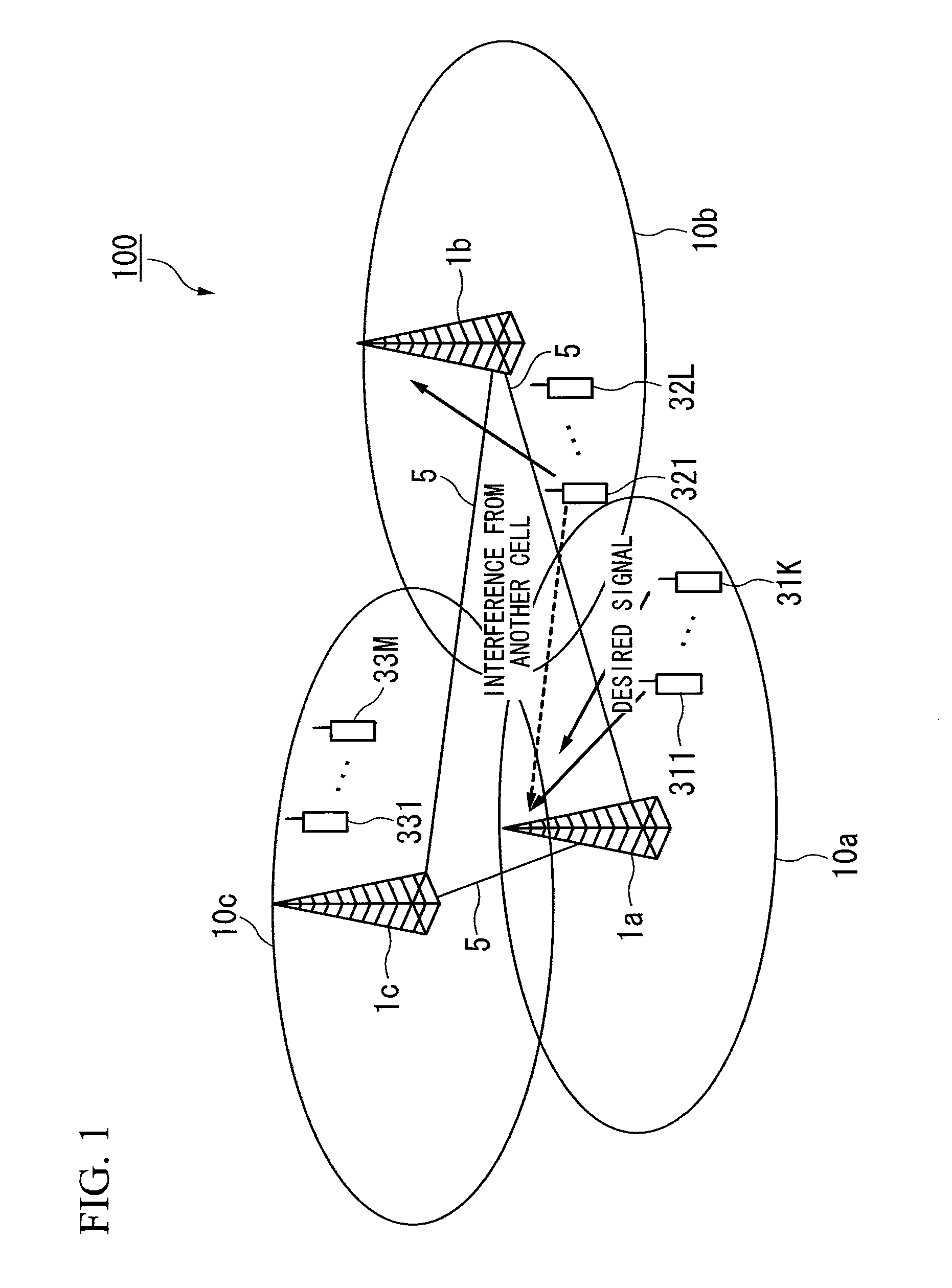
[0044]FIG. 1 is a schematic diagram showing an example structure of a wireless communication system 100 in the embodiment of the present invention. In FIG. 1, the wireless communication system 100 includes wireless base station apparatuses 1a, 1b, and 1c, and terminal devices 311, . . . , 31K, 321, . . . , 32L, 331, . . . , and 33M, where K, L, and M are natural numbers.

[0045]The wireless base station apparatuses 1a, 1b, and 1c have the same structure, where any one of them is called a “wireless base station apparatus 1” and two or more of them are collectively called “wireless base station apparatuses 1”. Similarly, the terminal devices 311, . . . , 31K, 321, . . . , 32L, 331, . . . , and 33M have the same structure, where any one of them is called a “terminal device 300” and t...


PUM


Abstract

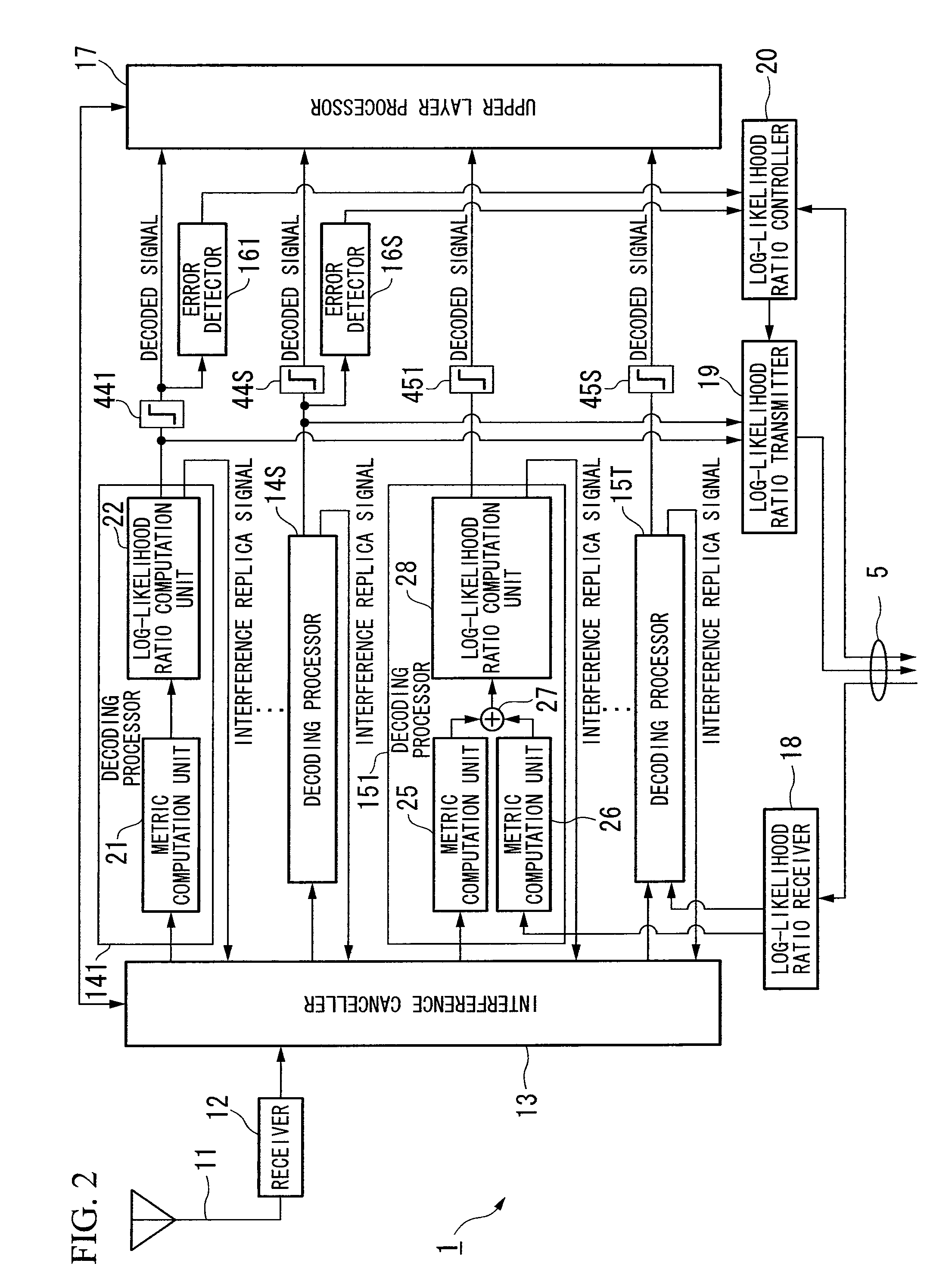
A wireless base station apparatus communicates with first terminal devices belonging to the present cell by means of IDMA. The apparatus receives signals sent from the first terminal devices and at least a signal sent from a second terminal device belonging to another cell; separately extracts each received signal from the first terminal devices and the second terminal device from the signals received by the receiver and computes a channel value for each received signal, by using interference replica signals; sends information for requesting a second wireless base station apparatus which communicates with the second terminal device to send a log-likelihood ratio obtained based on a signal received from the second terminal device; performs decoding using the channel value for each first terminal device, and generates a log-likelihood ratio as a decoding result and the corresponding interference replica signal; and performs decoding using the log-likelihood ratio received from said second wireless base station apparatus and the channel value for the second terminal device, and generates a log-likelihood ratio as a decoding result and the corresponding relevant interference replica signal.

Description

BACKGROUND OF THE INVENTION[0001]1. Field of the Invention[0002]The present invention basically relates to a wireless base station apparatus and a wireless communication method.[0003]Priority is claimed on Japanese Patent Application No. 2010-016856, filed Jan. 28, 2010, the contents of which are incorporated herein by reference.[0004]2. Description of the Related Art[0005]Accompanied with a recently increasing demand for wireless communication, in particular, by using a portable wireless terminal device, a technique for improving the efficiency of frequency usage has been actively performed.[0006]In Non-Patent Document 1, IDMA (interleave division multiple access) is proposed so as to identify each channel using a plurality of channel interleave patterns. In communication based on the IDMA method, instead of a spreading process of each terminal device during transmission in CDMA (code division multiple access), a wireless base station apparatus performs user separation using indivi...

Claims


Application Information

Patent Timeline
IPC IPC(8): H04W4/00
CPCH04J11/004H04L1/005H04J11/005
Inventor MATSUMOTO, TOMOKOKONISHI
Owner KDDI CORP
Learn More