
Thrust needle roller bearing with isolating layer

a technology of isolating layer and needle bearing, which is applied in the direction of rolling contact bearings, shafts and bearings, rotary bearings, etc., can solve the problems of causing vibration transmission, objectionable noise, and unacceptable wear of surfaces, and achieve the effect of preventing creep or sliding wear

Inactive Publication Date: 2011-07-28
SCHAEFFLER TECH AG & CO KG
View PDF7 Cites 11 Cited by
  • Summary
  • Abstract
  • Description
  • Claims
  • Application Information

AI Technical Summary

Benefits of technology

[0012]The isolating layer can act in a variety of capacities and can be comprised of various materials. The isolating layer can also be a layer of vibration-attenuating material, which reduces noise due to vibrations transmitted between the thrust bearing and the backup surfaces. Moreover, the isolating layer can be a layer of material with properties that prevent creep or sliding wear of the backup surfaces. The isolating layer is attachable to at least one of the washers by bonding, adhesive means, or mechanical means. Furthermore, the isolating layer must have adequate material properties and an adequate thickness to provide useful vibration attenuation or wear-reduction and must be able to withstand the operating environment (temperature, chemical, pressure, time) without unacceptable loss of attenuating or other physical properties, and without the compliant layer experiencing unacceptable wear.
[0015]In another embodiment, the isolating layer can be a layer of material having properties that prevent creep or sliding wear of the backup surface.

Problems solved by technology

When the bearing is operating under load and speed, imperfections in the roller roundness and on the raceway surface, or contamination present in the bearing, will create vibrations that are transmitted through the washers to the bearing's surfaces.
If the vibrations are of sufficient amplitude and in critical frequency ranges and if there is a free path for the vibration to the surface of the case, the result is objectionable noise.
Rotation or creep of the bearing washers against their backup surfaces may cause unacceptable wear of those surfaces.
Certain thrust bearings can result in perceived noise due to vibrations transmitted through the interface between the thrust bearing and its backup surface.
Additionally, excessive wear of the bearing's backup surface can occur due to relative motion.

Method used


Image

  • Thrust needle roller bearing with isolating layer
  • Thrust needle roller bearing with isolating layer

Examples


Embodiment Construction

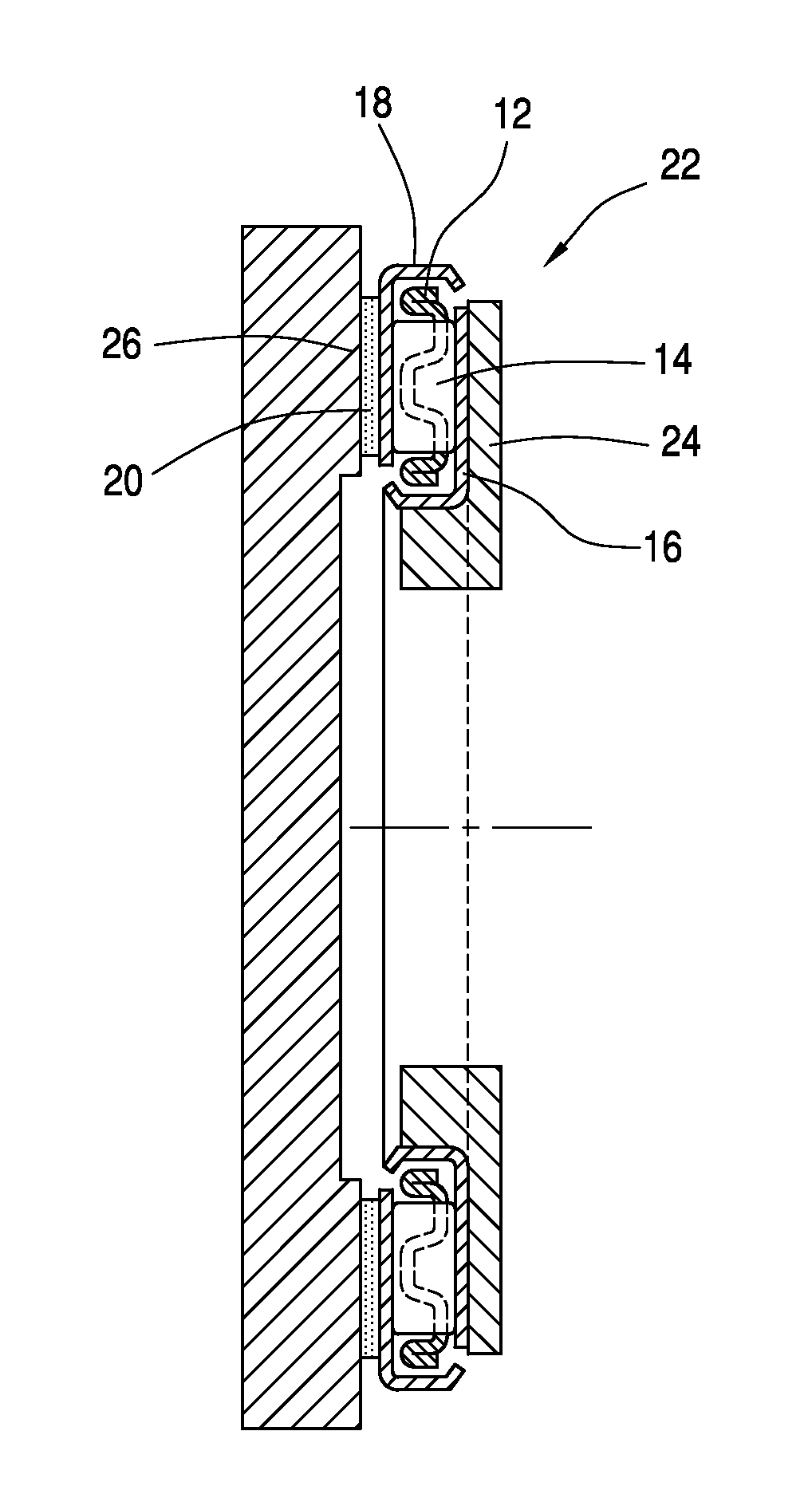
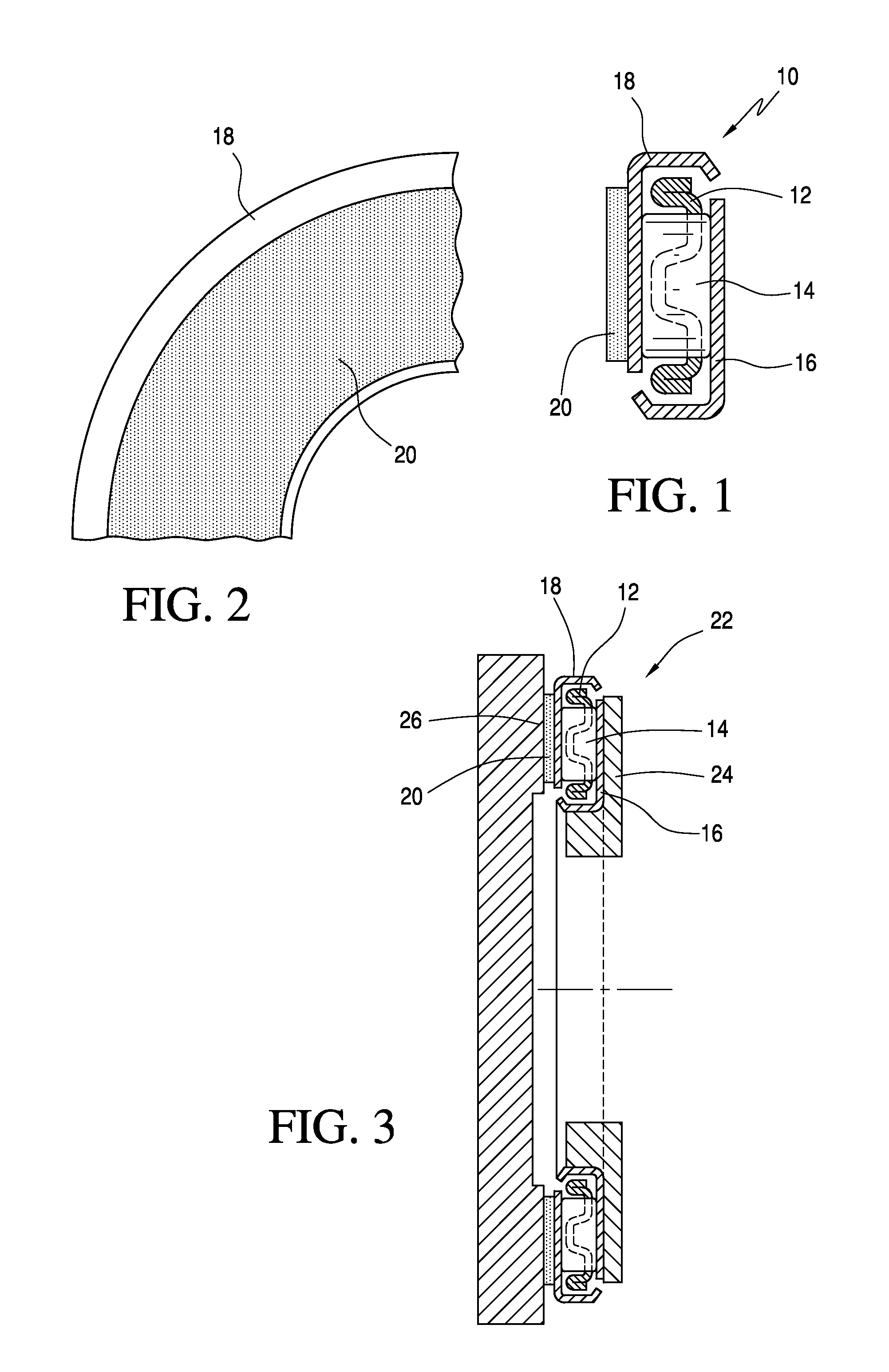
[0025]Referring now to the drawings, in which like reference numerals refer to like reference parts throughout, FIG. 1 shows a cross-sectional view of the thrust needle roller bearing 10. The thrust needle roller bearing 10 includes a cage 12 which contains rollers 14. Washers 16, 18, on which the rollers 14 roll, are attached on each side of the cage 12. An isolating layer 20 is interposed between at least one of the washers 16, 18 and a backup surface 24, 26 (see FIG. 3) of the bearing 10.

[0026]The isolating layer 20 can be a layer of vibration-attenuating material, which reduces noise due to vibrations transmitted between the thrust bearing 10 and the backup surfaces 24, 26 (see FIG. 3). Moreover, the isolating layer 20 can be a layer of material with properties that prevent creep or sliding wear of the backup surfaces 24, 26 (see FIG. 3). The isolating layer 20 is attachable to at least one of the washers 16, 18 by bonding, adhesive means, or mechanical means. The isolating laye...


PUM


Abstract

A thrust needle bearing with an isolating layer has a cage with rollers, washers on which the rollers run, at least one of the washers is attached to the cage, backup surfaces fixed external to each of the washers and an isolating layer attached to at least one of the washers, which is interposed between the at least one of the washers and at least one of the backup surfaces of the bearing. The isolating layer is a layer of vibration-attenuating material. Alternatively, the isolating layer is a layer of material which has properties that prevent creep or sliding wear for at least one of the backup surfaces. The isolating layer is attached to the washers by bonding, use of adhesives or mechanical means.

Description

FIELD OF INVENTION[0001]The present invention relates to thrust bearings. More particularly, the present invention relates to a thrust needle bearing assembly that has at least one layer of vibration-attenuating or wear-reducing material.BACKGROUND OF THE INVENTION[0002]Thrust needle bearings are used in transmissions, torque converters, and transfer cases to transfer thrust loads between adjacent components that operate with relative rotational speed. Thrust needle bearings allow the relative speed to occur with low friction. Typically, thrust bearings include a cage, which contains rollers, and washers on which the rollers run with the area of each washer contacting the rollers being a raceway. For convenience of assembly, one or both washers can be attached to the cage in a manner that allows free rotation for bearing function. Alternatively, one or both washers can be separate from the cage.[0003]When the bearing is operating under load and speed, imperfections in the roller rou...

Claims


Application Information

Patent Timeline
Patent Type & Authority Applications(United States)
IPC IPC(8): F16C33/34
CPCF16C19/30F16C33/34F16C27/04F16C19/46
Inventor BROWN, JAMESCLARK, ERICGRIFFIN, JOSEPH
Owner SCHAEFFLER TECH AG & CO KG
Learn More