Image forming apparatus, image density control method, control program and recording medium

a technology of image density and image forming apparatus, which is applied in the direction of electrographic process apparatus, instruments, optics, etc., can solve the problems of insufficient image density control to provide a further high-definition image, inability to achieve high-density correction with high precision, and insufficient to achieve high-density correction effectively. , to achieve the effect of optimal development potential and high precision

Inactive Publication Date: 2011-07-28
SHARP KK
View PDF6 Cites 6 Cited by
  • Summary
  • Abstract
  • Description
  • Claims
  • Application Information

AI Technical Summary

Benefits of technology

[0033]According to the sixth aspect of the present invention, since a greater number of toner image patches can be created around the target image density and detected on image density, it is possible to achieve high-density correction with higher precision.
[0034]According to the seventh aspect of the present invention, it is possible to achieve high-density correction effectively, without creating a greater number of toner image patches than needed.
[0035]According to the eighth aspect of the present invention, the optimal development potential can be obtained in a short time by implementing the next high-density correction earlier than usual.
[0036]According to the ninth aspect of the present invention, the approximate equation can be determined with precision by approximation using the least squares method based on, for example, the detected value obtained at the toner image density detecting step and the development potential by t...

Problems solved by technology

In the image forming apparatuses of this kind, it happens that the resultant toner image varies in image density due to variation of ambient conditions around the apparatus, fatigue of the photoreceptor and the developer, and the like.
For this purpose, it is necessary to provide fine adjustment of the development potential to attain the target image density, hence the...

Method used


Image

  • Image forming apparatus, image density control method, control program and recording medium
  • Image forming apparatus, image density control method, control program and recording medium
  • Image forming apparatus, image density control method, control program and recording medium

Examples


Embodiment Construction

[0044]The embodiment of the present invention will hereinafter be described in detail with reference to the accompanying drawings.

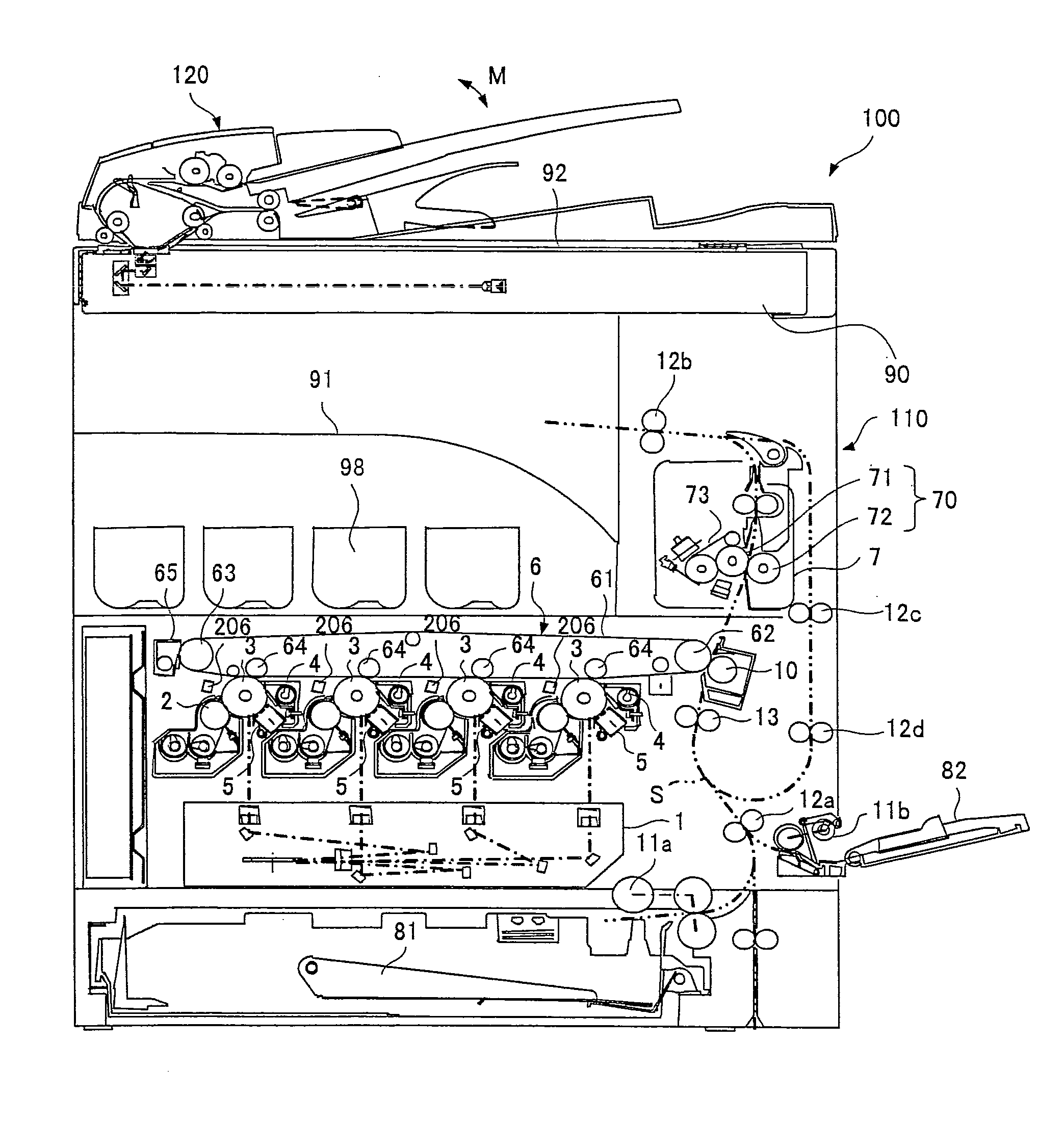
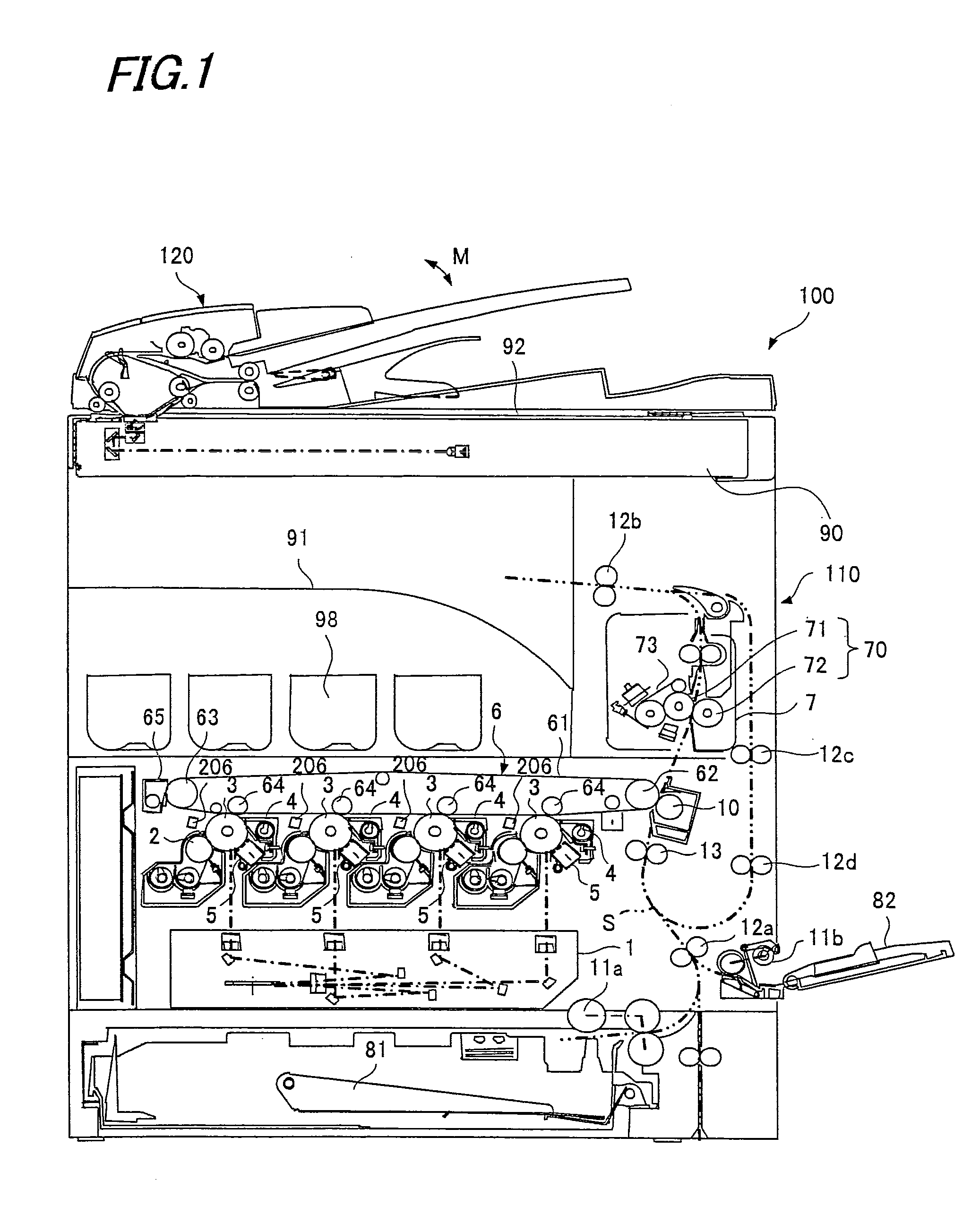
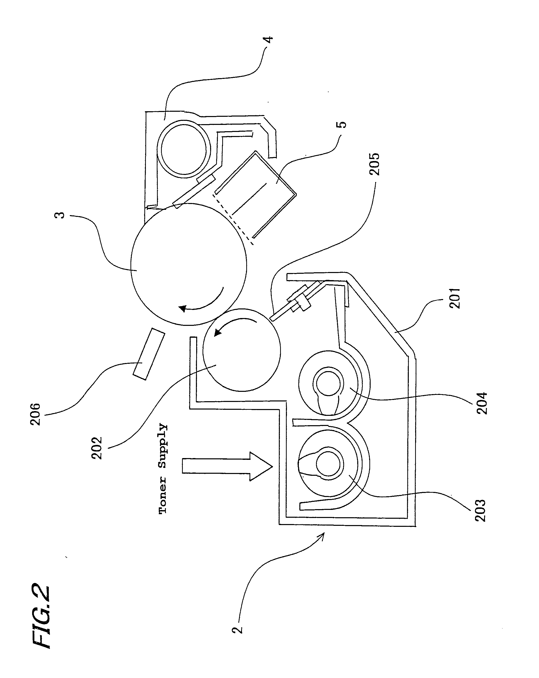
[0045]FIG. 1 shows one exemplary embodiment for carrying out the invention and is an illustrative view showing an overall configuration of an image forming apparatus according to the embodiment of the present invention. FIG. 2 is an illustrative view showing a developing unit and its peripheral configuration of the image forming apparatus. FIG. 3 is a block diagram showing an electric configuration of the image forming apparatus.

[0046]As shown in FIGS. 1 to 3, an image forming apparatus 100 of the present embodiment includes: a photoreceptor drum 3; a developing unit 2 having a development potential (developing bias) applied to form a toner image on photoreceptor drum 3; a photo sensor (toner image density detector) 206 for detecting the image density of the toner image formed as toner image patches on photoreceptor drum 3; an operation unit 306 for calcu...


PUM


Abstract

An image forming apparatus includes: a developing unit forming a toner image on a photoreceptor drum; a photo sensor detecting the image density of the toner image; an operation unit calculating a relational equation between the measurement detected by the photo sensor and the development potential; a storage unit storing the relational equation; and a control unit setting up a corrected development potential to obtain a target image density for the developing unit, based on the image density of toner image patches. When high-density correction is performed, the control unit forms a multiple number of toner image patches on the photoreceptor drum based on the corrected development potential that was obtained at the time of the previous high-density correction, and sets up a corrected development potential for obtaining the target image density, based on the multiple image densities of the multiple toner image patches.

Description

[0001]This Nonprovisional application claims priority under 35 U.S.C. §119(a) on Patent Application No. 2010-014978 filed in Japan on 27 Nov. 2010, the entire contents of which are hereby incorporated by reference.BACKGROUND OF THE INVENTION[0002](1) Field of the Invention[0003]The present invention relates to an image forming apparatus, image density control method, control program and recording medium, in particular, relating to an image forming apparatus such as an electrostatic copier, laser printer, facsimile machine or the like, which produces a toner image by use of an electrophotographic technique by applying a development potential to a photoreceptor, image forming method, control program and recording medium for use in this image forming apparatus.[0004](2) Description of the Prior Art[0005]Conventionally, image forming apparatuses based on electrophotography such as copiers, printers, facsimile machines and the like have been known. The image forming apparatus using elect...

Claims


Application Information

Patent Timeline
IPC IPC(8): G03G15/08
CPCG03G15/065G03G2215/00059H04N1/00015H04N1/00031G03G15/5041H04N1/00087H04N2201/0082G03G15/0131H04N1/00063
Inventor OTSUKA, MASAYUKIKITAGAWA, TAKASHINAGAYAMA, KATSUHIRO
Owner SHARP KK
Why Eureka
Try Eureka