Error management

a technology of error management and error detection, applied in the field of error management, can solve problems such as noise or distortion, data signal errors may be introduced at several stages, and achieve the effect of reducing engineering burden

Active Publication Date: 2011-07-28
ARM LTD
View PDF4 Cites 15 Cited by
  • Summary
  • Abstract
  • Description
  • Claims
  • Application Information

AI Technical Summary

Benefits of technology

[0012]The digital performance data provides the control circuitry with additional information for use in identifying where errors in the signal processing chain (e.g. RF channel, analogue circuitry and digital circuitry) are arising, enabling the control circuitry to make an informed decision to modify the operation of either the transmitting device or receiving device in some way, either to reduce the occurrence of errors in the output signal (if the error detection circuitry indicates that the number and type of errors in the output signal is too great) or to improve the speed and / or efficiency of the transmitter and / or receiver (if the error detection circuitry indicates that more errors can be tolerated). In this way, the performance of the transmitting device or receiving device can be improved and errors can be managed.
[0030]It is common for communication devices to use the error tolerance provided by error correction techniques to enable the use of a range of adaptive techniques to optimise for a range of factors in a particular environment. For example, mobile communication devices will typically incorporate adaptive mechanisms to maximise battery life, as well as other attributes such as latency or throughput, for example trading off the numbers of packets received / transmitted with error rate.
[0033]In the event of a corrupt packet being detected, it may however be beneficial to determine whether or not any timing errors were present during processing, as this information can be used to determine the best course of action. For example the raw packet could be re-processed using different operational parameters for the digital circuits, or a request could be made for the packet to be re-transmitted. Any information regarding timing errors does not have to be precise, as a system can be constructed which makes use of probabilistic timing error information, which relaxes the requirements on the error detection circuits used. Such probabilistic information can be regarded of a “quality of service” indicator for digital processing.
[0034]The present technique seeks to significantly reduce the engineering burden in applying circuit level timing speculation techniques to processors such as the Neon processor developed by ARM Limited, Cambridge, United Kingdom, running radio based protocol software, where the design is dominated by a clearly defined data path, and where errors in processing can be tolerated due to existing data integrity checks.

Problems solved by technology

In a communications system, when a data signal is transmitted from a transmitter to a receiver, errors may be introduced into the data signal at several stages.
For example, the transmission channel, which may be wired or wireless, may introduce noise or distortion (such as multipath distortion resulting from the interference of multiple reflections of the transmitted signal) into the data signal due to noise sources and interference, transmission medium irregularities, and attenuation of the data signal.
Furthermore, the analogue circuitry of the receiver, which will typically perform functions such as analogue signal amplification, frequency conversion and analogue to digital conversion, may also introduce noise into the data signal.
In either case these effects result in a loss of some of the data carried in the data signal.

Method used


Image

  • Error management
  • Error management
  • Error management

Examples


Embodiment Construction

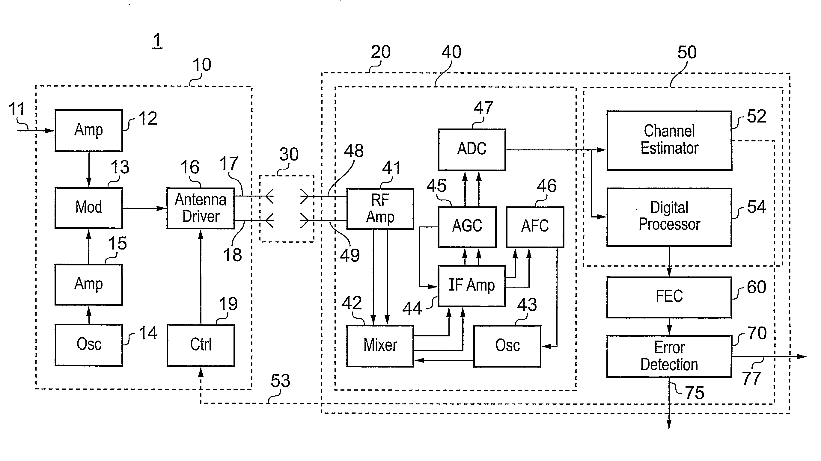
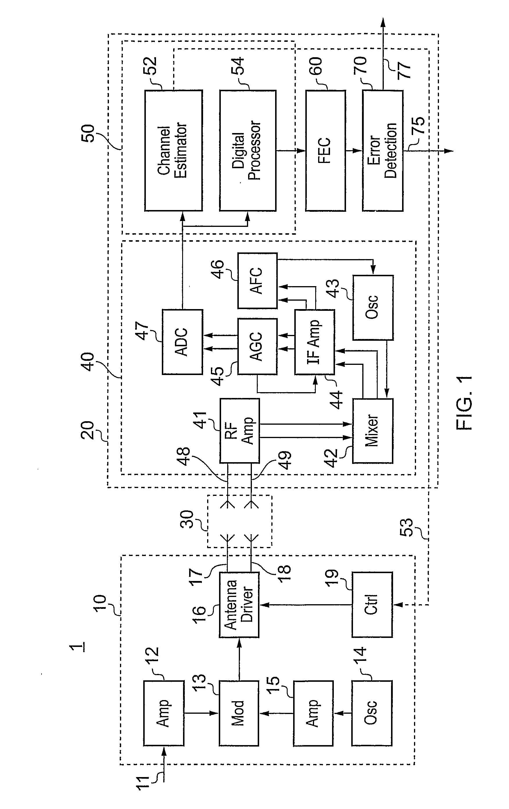
[0047]Referring to FIG. 1, an example communications system 1 is schematically illustrated. The communications system 1 comprises a transmitting apparatus 10 and a receiving apparatus 20 coupled together via a communications channel 30 which in the present case is a wireless communications channel. The transmitting apparatus 10 comprises a signal amplifier 12 which receives and amplifies an input signal 11, which may be an audio or video signal, or other data signal, and which in the present case is a packetised data signal. The amplified signal generated by the signal amplifier 12 is passed to a modulator 13. The transmitting apparatus 10 also comprises an oscillator 14 which generates a carrier signal upon which the amplified signal generated by the signal amplifier 12 is to be carried. The carrier signal generated by the oscillator 14 is then received and amplified by a carrier amplifier 15. The amplified carrier signal is then passed to the modulator 13. The modulator 13 is oper...


PUM


Abstract

An electronic device is described which receives data from a transmitting device via a communications channel. The electronic device comprises digital processing circuitry arranged to process the data received via the communications channel to generate output data, error detection circuitry arranged to detect errors in the output data, and monitoring circuitry arranged to monitor the quality of digital processing conducted by the digital processing circuitry and generate digital performance data indicative of the monitored quality of digital processing. The electronic device also comprises control circuitry responsive to error information comprising errors detected by the error detection circuitry and the performance data generated by the monitoring circuitry to modify the operation of one or both of the transmitting device and the electronic device. The digital performance data provides the control circuitry with additional information for use in identifying where errors in signal processing are arising, enabling an informed decision be made to modify the operation of either the transmitting device or receiving device in some way, either to reduce the occurrence of errors in the output signal or to improve the speed and / or efficiency of the transmitter and / or receiver.

Description

FIELD OF INVENTION [0001]The present invention relates to error management. More particularly, embodiments of the present invention relate to a receiving apparatus and method within a communications system which are responsive to detected errors to modify the operation of the communications system.BACKGROUND OF THE INVENTION[0002]In a communications system, when a data signal is transmitted from a transmitter to a receiver, errors may be introduced into the data signal at several stages. In particular, there are three main stages which can be considered, these being the transmission channel (wired or wireless) between the transmitter and the receiver, the analogue circuitry of the receiver, and the digital circuitry of the receiver. For example, the transmission channel, which may be wired or wireless, may introduce noise or distortion (such as multipath distortion resulting from the interference of multiple reflections of the transmitted signal) into the data signal due to noise so...

Claims


Application Information

Patent Timeline
Patent Type & Authority Applications(United States)
IPC IPC(8): H03M13/05G06F11/10
CPCH04B7/0619H04B7/0689H04B7/0691H04B17/336H04L1/0025H04L1/20H04L25/0202H04L1/0002
Inventor KERSHAW, DANIELBULL, DAVID MICHAELWILDER, MLADEN
Owner ARM LTD
Why Eureka
Try Eureka