Hydraulic brake system with controlled boost

a brake system and hydraulic technology, applied in the direction of braking systems, rotary clutches, fluid couplings, etc., can solve the problems of increased stopping distance, increased slippage between the wheel and the road surface, and possible loss of directional control

Active Publication Date: 2011-08-04
KELSEY HAYES CO
View PDF44 Cites 22 Cited by
  • Summary
  • Abstract
  • Description
  • Claims
  • Application Information

AI Technical Summary

Benefits of technology

[0011]This invention relates to a vehicle brake system which includes a brake pedal unit coupled to a vehicle brake pedal. The system includes an input piston connected to operate a pedal simulator during a normal braking mode, and coupled to actuate a pair of output pistons during a manual push through mode. The output pistons are operable to generate brake actuating pressure at first and second outputs of the brake pedal unit. A hydraulic pressure source supplies fluid at a controlled boost pressure. A hydraulic control unit is adapted to be hydraulically connected to the brake pedal unit and the hydraulic pressure source. The hydraulic control unit includes a slip control valve arrangement, and a switching base brake valve arrangement for switching the brake system between the normal braking mode wherein boost pressure from the pressure source is supplied to first and second vehicle brakes, and the manual push through mode wherein brake actuating pressure from the brake pedal unit is supplied to the first and second vehicle brakes. The input piston cooperates with a seal mounted in the brake pedal unit to provide for a progressive rate of friction therebetween as the input piston is advanced in the brake pedal unit by the brake pedal.
[0012]This invention also relates to a vehicle brake system including a brake pedal unit coupled to a vehicle brake pedal. The system includes an input piston connected to operate a pedal simulator during a normal braking mode, and coupled to actuate a pair of output pistons during a manual push through mode. The output pistons are operable to generate brake actuating pressure at first and second outputs of the brake pedal unit. A hydraulic pressure source supplies fluid at a controlled boost pressure. A hydraulic control unit is adapted to be hydraulically connected to the brake pedal unit and the hydraulic pressure source. The hydraulic control unit includes a slip control valve arrangement, and a switching base brake valve arrangement for switching the brake system between the normal braking mode wherein boost pressure from the pressure source is supplied to first and second vehicle brakes, and the manual push through mode wherein brake actuating pressure from the brake pedal unit is supplied to the first and second vehicle brakes. The pedal simulator applies an opposing feedback force to the input piston and brake pedal during brake application. The pedal simulator defines a fluid chamber in communication with a fluid reservoir via a conduit. An orifice is disposed in the conduit to restrict the flow of fluid therethrough such that the orifice cooperates with the input piston to provide progressive damping to impede the advancement of the input piston as the input piston is advanced in the brake pedal unit.
[0013]This invention may also relate to a vehicle brake system including a brake pedal unit coupled to a vehicle brake pedal. The brake pedal unit includes an input piston connected to operate a pedal simulator during a normal braking mode, and coupled to actuate a pair of output pistons during a manual push through mode. The output pistons are operable to generate brake actuating pressure at first and second outputs of the brake pedal unit. A hydraulic pressure source supplies fluid at a controlled boost pressure. A hydraulic control unit is adapted to be hydraulically connected to the brake pedal unit and the hydraulic pressure source. The hydraulic control unit includes a slip control valve arrangement, and a switching base brake valve arrangement for switching the brake system between the normal braking mode wherein boost pressure from the pressure source is supplied to first and second vehicle brakes, and the manual push through mode wherein brake actuating pressure from the brake pedal unit is supplied to the first and second vehicle brakes. The brake pedal unit includes a cushion for cushioning the input piston back to a rest position when the brake pedal has not been actuated.

Problems solved by technology

Under these conditions, a driver can easily apply excessive braking pressure thus causing one or more wheels to lock, resulting in excessive slippage between the wheel and road surface.
Such wheel lock-up conditions can lead to greater stopping distances and possible loss of directional control.
Excessive wheel speed during vehicle acceleration leads to wheel slippage and a loss of traction.
During vehicle motion such as cornering, dynamic forces are generated which can reduce vehicle stability.
Preferably, the hydraulic braking operates in a regenerative brake blending manner so that the blending is effectively and unnoticeably picked up where the electromagnetic braking left off.

Method used


Image

  • Hydraulic brake system with controlled boost
  • Hydraulic brake system with controlled boost
  • Hydraulic brake system with controlled boost

Examples


first embodiment

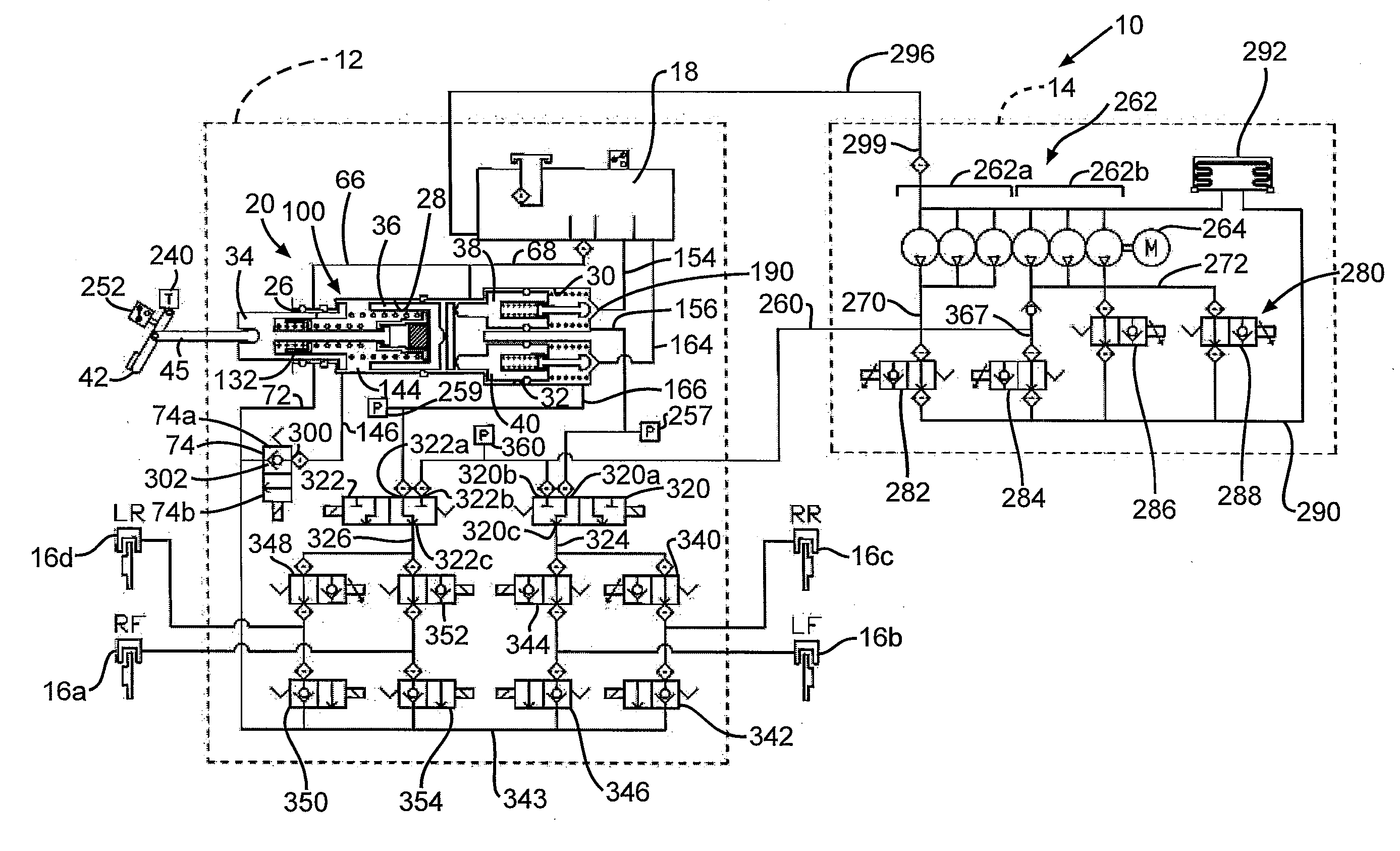
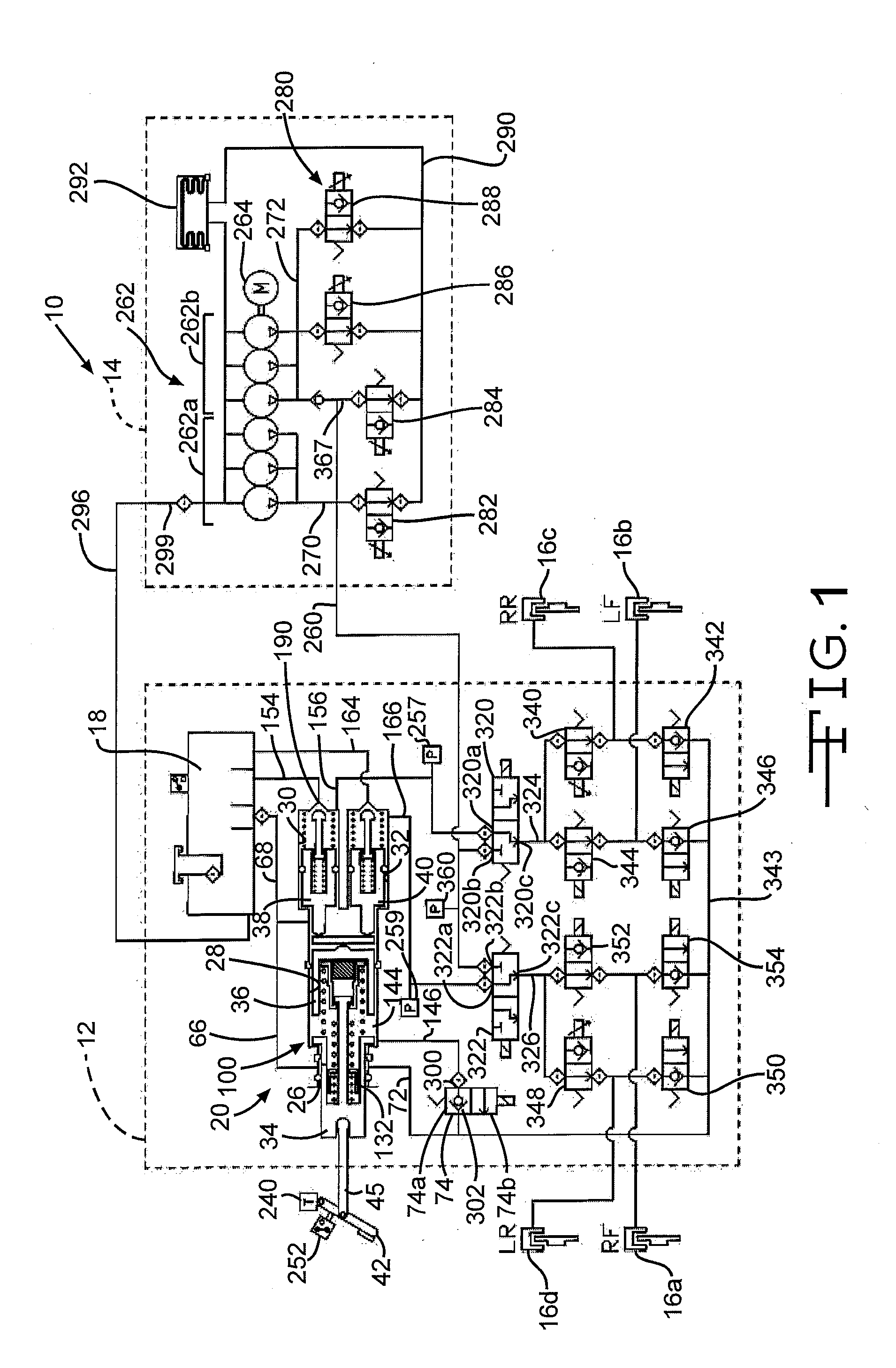
[0033]Referring now to the drawings, there is schematically illustrated in FIG. 1 a vehicle brake system, indicated generally at 10. The brake system 10 is a hydraulic boost braking system in which boosted fluid pressure is utilized to apply braking forces for the brake system 10. The brake system 10 may suitably be used on a ground vehicle such as an automotive vehicle having four wheels with a wheel brake associated with each wheel. Furthermore, the brake system 10 can be provided with other braking functions such as anti-lock braking (ABS) and other slip control features to effectively brake the vehicle, as will be discussed below.

[0034]The brake system 10 generally includes a hydraulic control unit, indicated by broken lines 12, and a power pack assembly, indicated by broken lines 14. The components of the hydraulic control unit 12 may be housed together in a single unit or block. The components of the power pack assembly 14 may also be housed in a single unit or block. As schem...

second embodiment

[0062]There is illustrated in FIG. 6 a vehicle brake system indicated generally at 400. Similar to the above described brake system 10, the brake system 400 may suitably be used on a ground vehicle such as an automotive vehicle having four wheels and a wheel brake for each wheel. Furthermore, the brake system 400 can be provided with other braking functions such as anti-lock braking (ABS), other slip control features, and regenerative braking blending to effectively brake the vehicle. The brake system 400 is similar in function and structure of some aspects of the brake system 10 and, therefore, like numbers and or names may be used to reference similar components.

[0063]The brake system 400 generally includes a hydraulic control unit which may be the same hydraulic control unit 12 as described above with respect to FIGS. 1-5. One of the differences between the systems 10 and 400 is that the brake system 400 uses a different power pack assembly 414. The power pack assembly 414 provid...

third embodiment

[0071]There is illustrated in FIG. 7 a vehicle brake system indicated generally at 460. Similar to the above described brake systems 10 and 400, the brake system 460 may suitably be used on a ground vehicle such as an automotive vehicle having four wheels and a wheel brake for each wheel. Furthermore, the brake system 460 can be provided with other braking functions such as anti-lock braking (ABS), other slip control features and regenerative brake blending to effectively brake the vehicle. The brake system 460 is similar in function and structure to the brake system 400 (and the brake system 10) and, therefore, like numbers and or names may be used to reference similar components.

[0072]The brake system 460 generally includes the same components as the brake system 400 illustrated in FIG. 6, but packages the components differently. In the brake system 460, a hydraulic control unit 462 includes the brake pressure unit 20, the reservoir 18, and the simulation valve 74. The remainder o...


PUM


Abstract

A vehicle brake system includes a brake pedal unit coupled to a vehicle brake pedal. The system includes an input piston connected to operate a pedal simulator during a normal braking mode, and coupled to actuate a pair of output pistons during a manual push through mode. The output pistons are operable to generate brake actuating pressure at first and second outputs of the brake pedal unit. A hydraulic pressure source supplies fluid at a controlled boost pressure. A hydraulic control unit is adapted to be hydraulically connected to the brake pedal unit and the hydraulic pressure source. The hydraulic control unit includes a slip control valve arrangement, and a switching base brake valve arrangement for switching the brake system between the normal braking mode wherein boost pressure from the pressure source is supplied to first and second vehicle brakes, and the manual push through mode wherein brake actuating pressure from the brake pedal unit is supplied to the first and second vehicle brakes. The input piston cooperates with a seal mounted in the brake pedal unit to provide for a progressive rate of friction therebetween as the input piston is advanced in the brake pedal unit by the brake pedal.

Description

CROSS-REFERENCE TO RELATED APPLICATIONS[0001]This application claims the benefit of International Application No. PCT / US10 / 023,121, filed Feb. 3, 2010.BACKGROUND OF THE INVENTION[0002]This invention relates in general to vehicle braking systems. Vehicles are commonly slowed and stopped with hydraulic brake systems. These systems vary in complexity but a base brake system typically includes a brake pedal, a tandem master cylinder, fluid conduits arranged in two similar but separate brake circuits, and wheel brakes in each circuit. The driver of the vehicle operates a brake pedal which is connected to the master cylinder. When the brake pedal is depressed, the master cylinder generates hydraulic forces in both brake circuits by pressurizing brake fluid. The pressurized fluid travels through the fluid conduit in both circuits to actuate brake cylinders at the wheels to slow the vehicle.[0003]Base brake systems typically use a brake booster which provides a force to the master cylinder ...

Claims


Application Information

Patent Timeline
Patent Type & Authority Applications(United States)
IPC IPC(8): B60T13/138B60T13/12
CPCB60T7/042B60T8/363B60T8/4086B60T11/224B60T13/686B60T8/409
Inventor GANZEL, BLAISE
Owner KELSEY HAYES CO
Why Eureka
Try Eureka