Motor phase winding fault detection method and apparatus

a technology of motor phase winding and fault detection, which is applied in the direction of motor/generator/converter stopper, dynamo-electric converter control, instruments, etc., can solve problems such as phase imbalance, motor phase winding may have minor manufacturing defects, and breakdown of surrounding winding insulation material

Inactive Publication Date: 2011-08-04
GM GLOBAL TECH OPERATIONS LLC
View PDF27 Cites 40 Cited by
  • Summary
  • Abstract
  • Description
  • Claims
  • Application Information

AI Technical Summary

Benefits of technology

[0006]The method set forth herein may be embodied in algorithmic form and executed via a motor controller to detect a predetermined phase winding fault. Phase impedance imbalance in motor phases introduces a negative sequence in motor currents for open loop control. In the case of field-oriented current control, the controller tries to keep the phase currents symmetrical and balanced up to a certain extent. As a result, a negative sequence is introduced into the various phase voltages.
[0007]The algorithm includes measuring a set of motor control values, and then performing a series of calculations and threshold-based comparisons to determine the presence of a predetermined phase winding fault. At least three different calculations may be made, thereby diagnosing the phase winding fault in a multitude of ways.

Problems solved by technology

Regardless of whether they are used in synchronous-type or in induction-type electric machines, motor phase windings may have minor manufacturing defects between turns or slots, or may develop such defects over time.
The defects, although minor, may cause a phase imbalance.
However, over an extended period any incipient defects in the phase windings can lead to a breakdown in the surrounding winding insulation material, which may ultimately lead to other defects or performance issues, such as open and / or shorted phase windings.

Method used


Image

  • Motor phase winding fault detection method and apparatus
  • Motor phase winding fault detection method and apparatus
  • Motor phase winding fault detection method and apparatus

Examples


Embodiment Construction

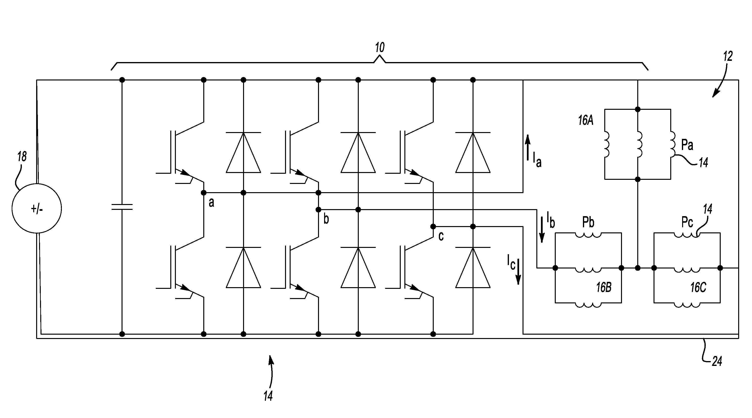
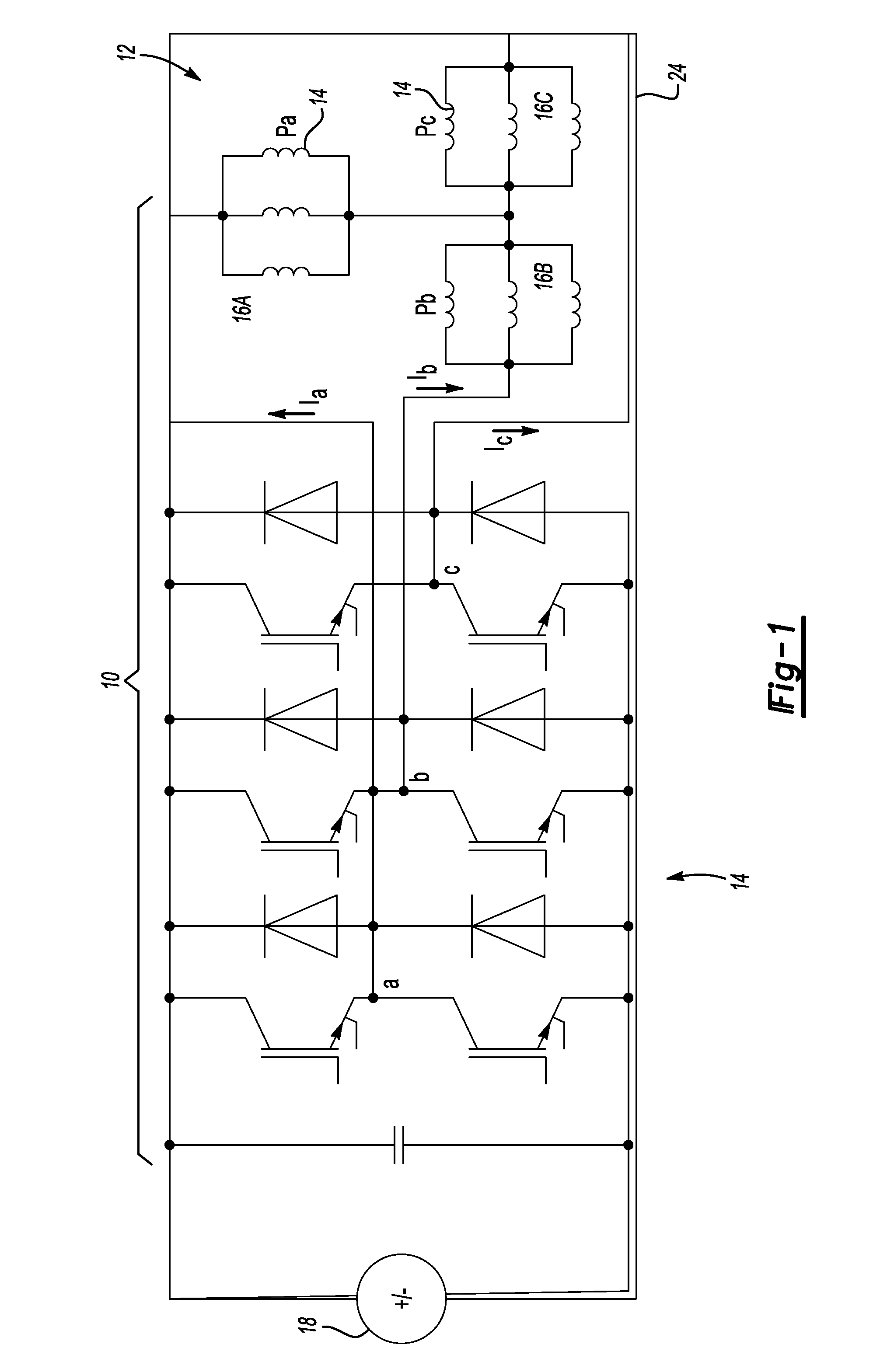
[0015]With reference to the drawings, wherein like reference numbers refer to the same or similar components throughout the several views, and beginning with FIG. 1, an electrical circuit 10 includes a poly-phase electric machine 12, i.e., a synchronous or induction-type motor / generator of the type known in the art, and a power or voltage-source inverter 14. The electric machine 12 includes multiple sets of phase windings, respectively labeled 16A, 16B, and 16C. Each set of phase windings 16A-C includes conductive windings or coils 15. The phase windings 16A, 16B, 16C carry a respective first, second, and third phase, labeled Pa, Pb, and Pc, respectively.

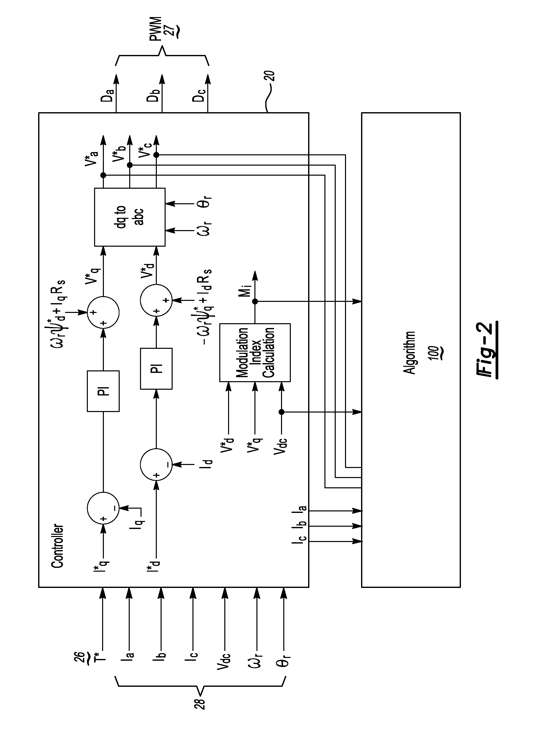
[0016]The inverter 14 may be electrically connected to a voltage supply 18, such as a direct current (DC) battery or other DC power supply. The inverter 14 is in communication with and controllable by a motor controller (C) 20 (see FIG. 2) having a phase winding fault detection algorithm 100, as will be described below with referenc...


PUM


Abstract

A method of detecting a phase winding fault in a multi-phase electric machine is executable via a motor controller, and includes measuring feedback signals of the machine, including each phase current, and generating reference phase voltages for each phase. The method includes calculating a predetermined voltage value using the feedback signals and reference phase voltages, and comparing the voltage value to a corresponding threshold to determine the fault. A control action is executed when the voltage value exceeds the corresponding threshold. The voltage value is one or more of: a ratio of a normalized negative sequence voltage to a modulation index, an RMS voltage for each phase, and total harmonic distortion of each phase current. An apparatus detects the fault, and includes a motor controller and an algorithm as set forth above. The apparatus may include a voltage inverter for generating a multi-phase alternating current output for powering the machine.

Description

TECHNICAL FIELD[0001]The present invention relates generally to the diagnostics of a poly-phase electric machine, and in particular to a method and apparatus for detecting a fault in a phase winding thereof.BACKGROUND OF THE INVENTION[0002]Electric power may be produced using poly-phase electric machines, also referred to as motor / generators. Synchronous electric machines may operate at constant speeds and frequencies under steady-state conditions. Synchronous electric machines, e.g., permanent magnet (PM) motors, operate via the principal of electromagnetic induction, with an electromotive force (EMF) generated via an induced flux by relative motion of conductive coils or windings. A synchronous electric machine typically includes a magnetic field structure and an armature. The armature may have a three-phase load winding, which in turn generates an alternating current (AC) EMF. In particular, a stationary or stator portion of a three-phase synchronous electric machine carries the ...

Claims


Application Information

Patent Timeline
Patent Type & Authority Applications(United States)
IPC IPC(8): G01R31/06
CPCG01R31/06G01R31/343
Inventor ANWAR, MOHAMMAD N.HASAN, S.M. N.RAHMAN, KHWAJA M.HITI, SILVASCHULZ, STEVEN E.GLEASON, SEAN E.
Owner GM GLOBAL TECH OPERATIONS LLC
Why Eureka
Try Eureka