Optical module

Active Publication Date: 2011-08-04
LUMENTUM JAPAN INC
View PDF2 Cites 2 Cited by
  • Summary
  • Abstract
  • Description
  • Claims
  • Application Information

AI Technical Summary

Benefits of technology

[0009]An object of the present invention is to achieve a size-reduction of an optical module having a circuit that generates a high-frequency clock signal for controlling optical modulation by an optical modulator and to suppress radiation of electromagnetic waves from the optical module.

Problems solved by technology

As a result, there is a problem in that radiation of the electromagnetic waves from the optical module is not suppressed as expected.

Method used


Image

  • Optical module
  • Optical module
  • Optical module

Examples


Embodiment Construction

[0022]Hereinafter, an embodiment of the present invention will be described with reference to the drawings.

[Optical Transceiver]

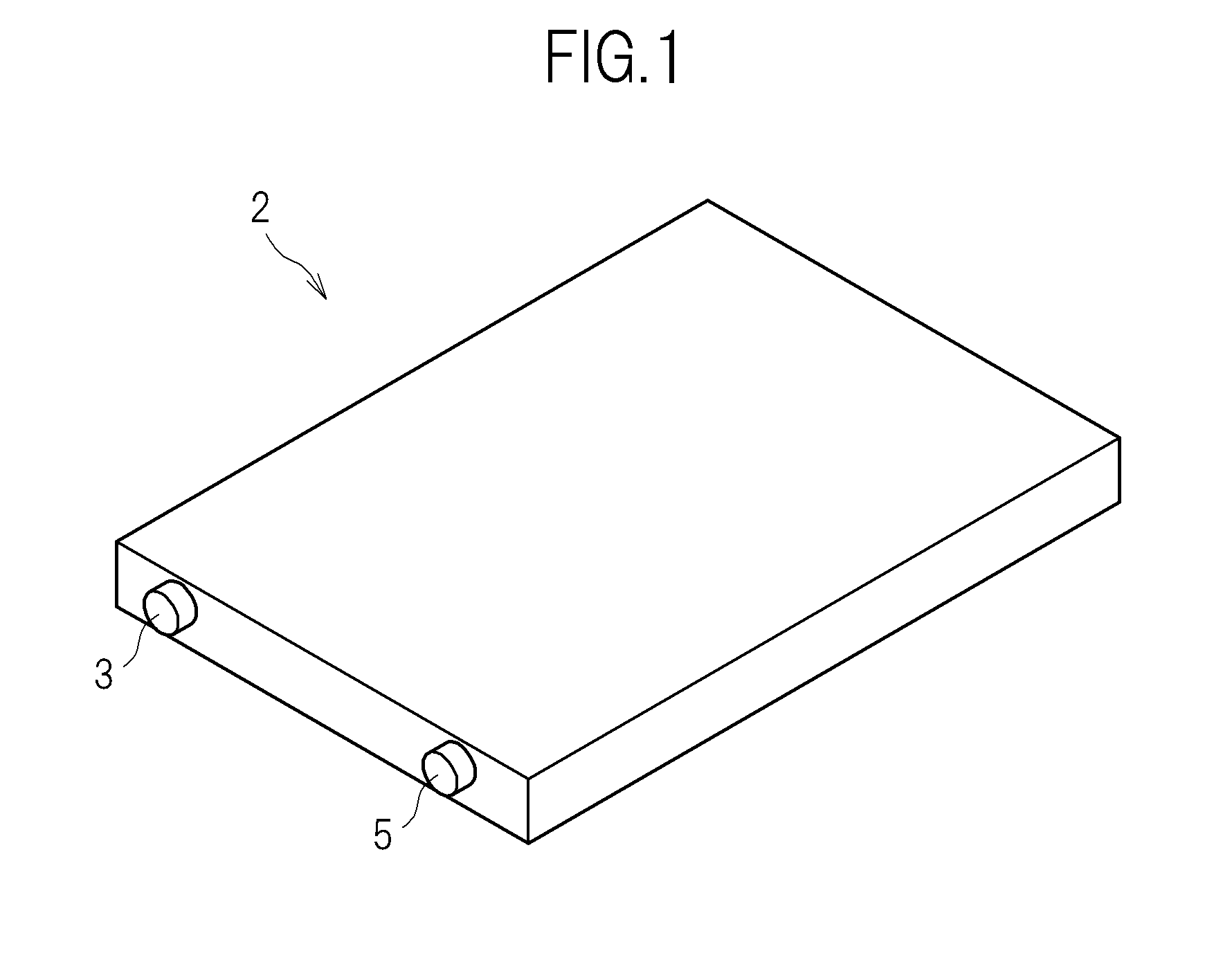
[0023]FIG. 1 shows an external appearance of an optical transceiver 2 which is an optical module according to an embodiment of the present invention. As shown in FIG. 1, the optical transceiver 2 includes two bushes 3 and 5, and an optical fiber (not shown) is connected to each bush. In the present embodiment, an optical signal is received through the bush 3, and an optical signal is transmitted through the bush 5. The bushes 3 and 5 are formed of conductive rubber, for example.

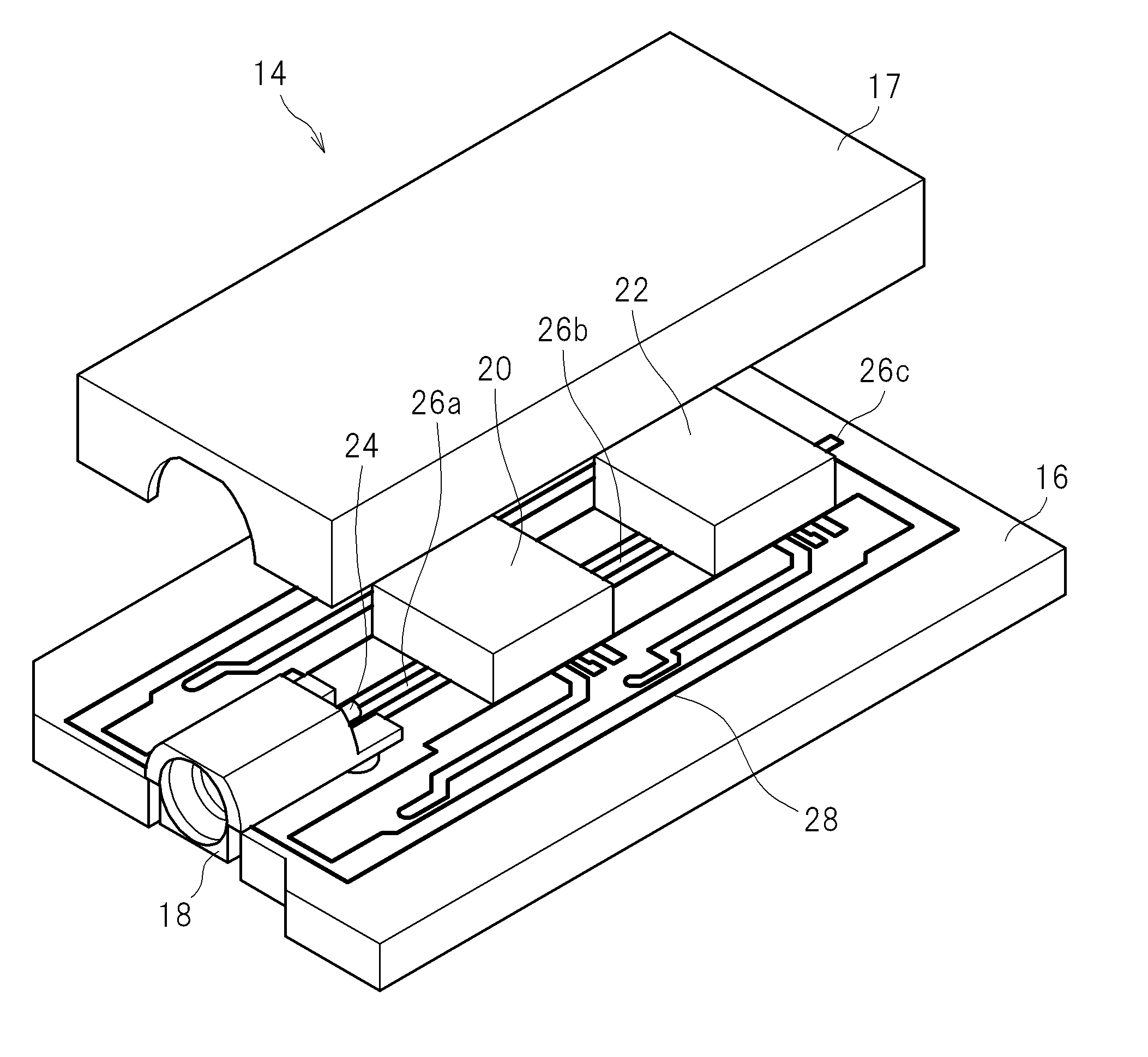
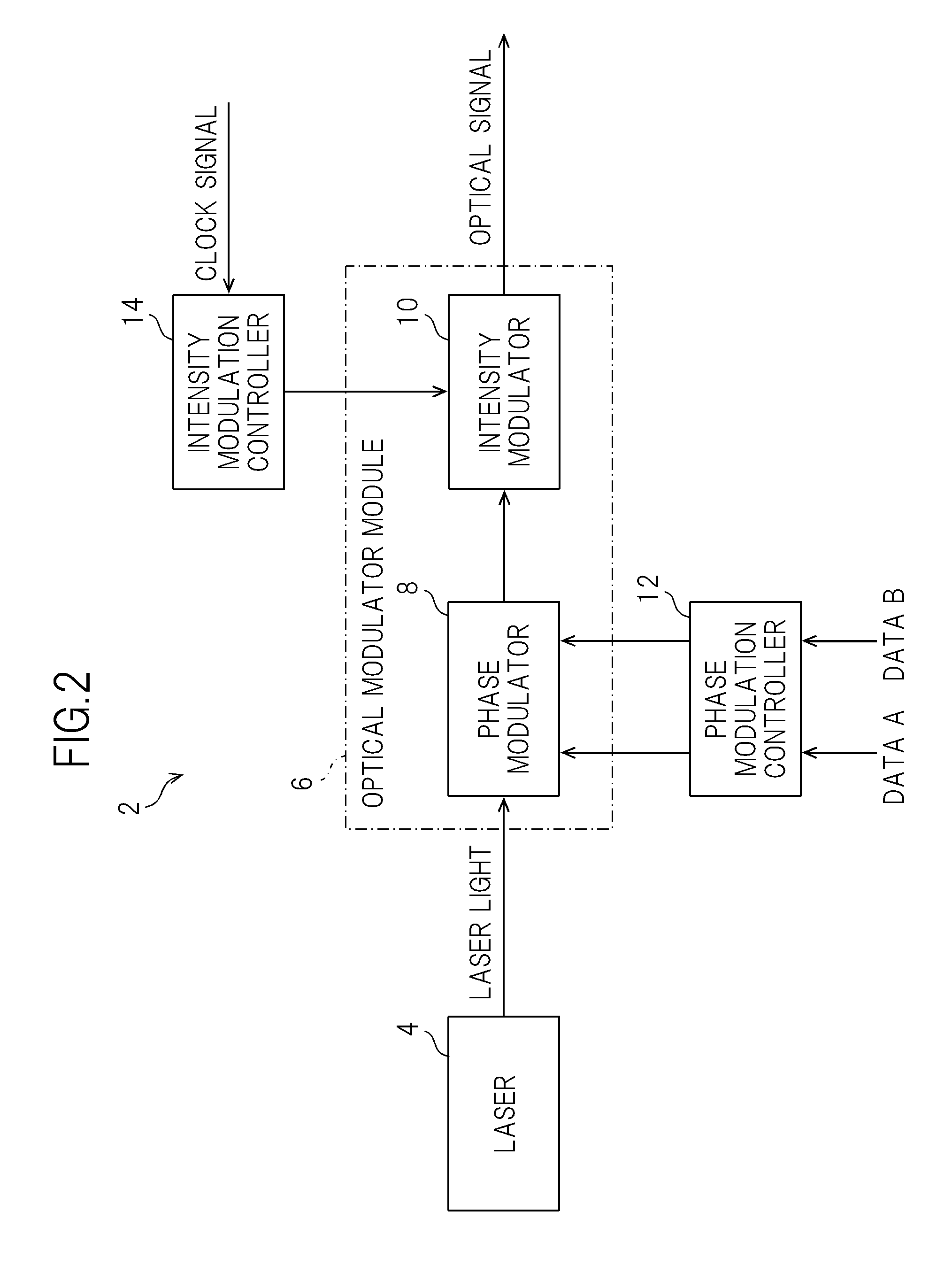
[0024]FIG. 2 shows the configuration of the optical transceiver 2. The optical transceiver 2 includes a device which forms a transmission module used for transmitting an optical signal and a device which forms a reception module used for receiving an optical signal. FIG. 2 shows a device which forms a transmission module.

[0025]As shown in FIG. 2, the optical transceiver 2 includes a ...


PUM


Abstract

To achieve a size-reduction of an optical module having a circuit that generates a high-frequency clock signal for controlling optical modulation by an optical modulator and to suppress radiation of electromagnetic waves from the optical module. A through-hole via is formed on a multilayer printed circuit board so as to be insulated from a plurality of grounded wiring layers by an anti-pad. A coaxial connector and an intensity modulation control IC that generates a high-frequency clock signal are provided on the multilayer printed circuit board. The high-frequency clock signal is input to the coaxial connector through a micro-strip line formed on the multilayer printed circuit board. An open stub connected to the through-hole via is provided on a wiring layer between a first wiring layer and a second wiring layer among the plurality of wiring layers.

Description

CROSS-REFERENCE TO RELATED APPLICATION[0001]The present application claims priority from Japanese application JP 2010-019362 filed on Jan. 29, 2010, the content of which is hereby incorporated by reference into this application.BACKGROUND OF THE INVENTION[0002]1. Field of the Invention[0003]The present invention relates to an optical module.[0004]2. Description of the Related Art[0005]An optical module such as an optical transceiver which includes a circuit that generates a high-frequency clock signal for controlling optical modulation (for example, so-called RZ (Return to Zero) modulation) by an optical modulator (for example, an LN modulator) is known. JP2007-82094A discloses an optical transmission device having such a circuit.SUMMARY OF THE INVENTION[0006]A case where a high-frequency clock signal generated by the circuit described above is supplied to an optical modulator through a coaxial cable will be considered. In this case, in order to decrease the size of an optical modul...

Claims


Application Information

Patent Timeline
IPC IPC(8): G02F1/01
CPCG02F1/01G02F1/0121G02F1/0356G02F1/2255
Inventor KAGAYA, OSAMUNAKAGAWA, HIROFUMIKOGURE, TAICHI
Owner LUMENTUM JAPAN INC
Why Eureka
Try Eureka