Millimeter-wave wideband low-sidelobe horn antenna

A horn antenna and low sidelobe technology, applied in the field of millimeter wave imaging and measurement, can solve the problems of long processing time and increased processing cost, and achieve the effects of good product consistency, low unit cost, and low radiation sidelobe

Pending Publication Date: 2019-04-12
NANJING UNIV OF INFORMATION SCI & TECH
View PDF8 Cites 2 Cited by
  • Summary
  • Abstract
  • Description
  • Claims
  • Application Information

AI Technical Summary

Problems solved by technology

However, this continuous gradient segment structure poses certain challenges to the CNC milling process. The higher the smoothness requirement, the longer the processing time, which indirectly leads to an increase in processing costs.

Method used


Image

  • Millimeter-wave wideband low-sidelobe horn antenna
  • Millimeter-wave wideband low-sidelobe horn antenna
  • Millimeter-wave wideband low-sidelobe horn antenna

Examples


Embodiment Construction

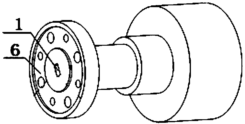
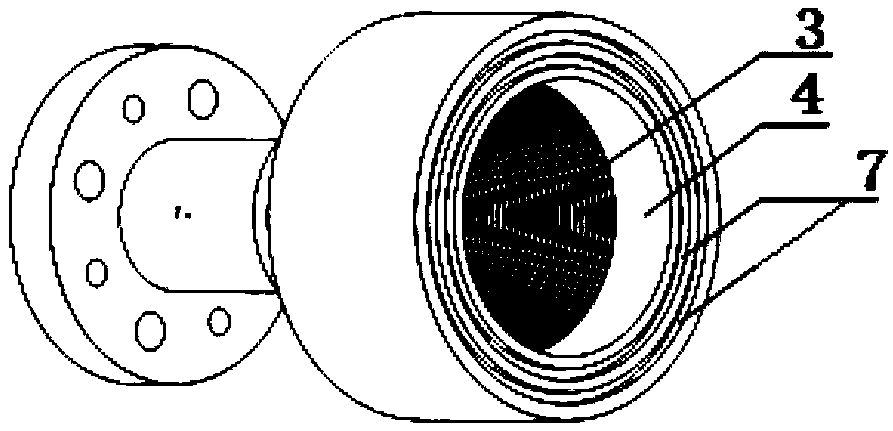
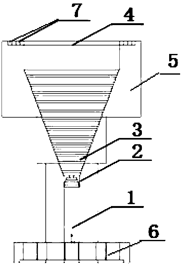
[0027] like figure 1 , figure 2 , image 3 and Figure 4 The main technical specifications of the millimeter-wave broadband low-sidelobe horn antenna shown are as follows:

[0028] Working frequency band: 76-81GHz

[0029] Gain: >20dBi

[0030] In-band VSWR: <1.5

[0031] 3dB beam width: >15 degrees

[0032] Side lobe suppression: >20dB

[0033] Polarization isolation: >20dB

[0034] The electromagnetic radiation area is formed by sequentially setting a rectangular feed waveguide 1, a rectangular transition section 2, a circular step transition section 3, and a circular radiation surface 4 according to the transmission direction of the electromagnetic wave; the rectangular transition section 2 is used to realize the rectangular feed The conversion between the waveguide 1 and the circular step transition section 3, the circular step transition section 3 gradually expands the circular opening surface of the last stage of the oblong transition section 2 to the last stage...


PUM


Abstract

The invention discloses a millimeter-wave wideband low-sidelobe horn antenna. A rectangular feeding waveguide, a rectangular circular transition segment, a round stepped transition segment, a round radiation aperture surface are sequentially arranged along a transferring direction of an electromagnetic wave to form an electromagnetic radiation region, wherein the rectangular circular transition segment is used for achieving conversion from the rectangular feeding waveguide to the round stepped transition segment, the round stepped transition segment is used for gradually expanding a round aperture surface of the last stage of the rectangular round transition segment to the tail-stage aperture surface by a plurality of steps, and a matching segment is extended from the tail-stage aperture surface at equal width to form the round radiation aperture surface. The horn antenna employs a stepped transition radiation segment to substitute a continuous transition radiation segment, a structureof a wave limitation groove is integrated at the periphery of the radiation aperture surface, the proposed antenna has the integrated structure characteristic and can be implemented purely by a conventional mechanical processing technology, other complicated processed are not needed to help, subsequent splicing assembly is not needed, the product consistency is good, and a single piece is low incost, wide in frequency band and low in radiation sidelobe.

Description

technical field [0001] The invention relates to the field of millimeter wave imaging and measurement, in particular to a millimeter wave broadband low side lobe horn antenna. Background technique [0002] The horn antenna is widely used in radar, communication and measurement systems because of its mature design method, relatively simple structure, wide operating frequency band, and high radiation efficiency. The radiation aperture area is formed. Horn antennas are generally divided into pyramidal horn antennas and conical horn antennas. These two antennas have the following characteristics in terms of structural technology and radiation beam performance. In some occasions, there will be some restrictions on their manufacture and use: [0003] First of all, in terms of structural technology, pyramidal horn antennas are mostly realized by sheet metal technology combined with silver welding technology, and conical horn antennas are mostly processed by electroforming technolog...

Claims


Application Information

Patent Timeline
Patent Type & Authority Applications(China)
IPC IPC(8): H01Q13/02H01Q1/50
CPCH01Q1/50H01Q13/02
Inventor 陈振华滕鹏
Owner NANJING UNIV OF INFORMATION SCI & TECH
Why Eureka
Try Eureka